Eureka AIR delivers breakthrough ideas for toughest innovation challenges, trusted by R&D personnel around the world.

Device for Storing Low-Molecular Gases

Inactive Publication Date: 2013-07-11
DAIMLER AG
View PDF4 Cites 3 Cited by
  • Summary
  • Abstract
  • Description
  • Claims
  • Application Information

AI Technical Summary

Benefits of technology

The invention provides a structure for storing gas in a compressed state, which has the advantage of requiring less resources and reducing gas losses. However, the structure also encourages the diffusion of gas through the inner shell, which can accelerate the diffusion process. This is particularly useful in fuel cell vehicles, where the structure can store a sufficient amount of hydrogen to achieve a good operating range of the vehicle without the risk of emergency disconnection during filling.

Problems solved by technology

If low molecular gases, in particular hydrogen, are stored under high pressure in the device for storing gas, it is practically unavoidable that small quantities of the low molecular gas will diffuse through the device and flow into the environment.
This is generally unproblematic due to the comparatively small quantity.
In case of a virtually empty compressed gas storage element, however, significant problems can arise.
If the leak-tightness of the compressed gas storage elements is determined via corresponding detectors, in particular the leak-tightness of the compressed gas storage elements used to store combustion gas in vehicles, this concentration is typically so high that an alarm is triggered and this generally leads to an emergency disconnection of the system, for example to an emergency cessation of filling.
The structure thereby has the disadvantage that it requires comparatively high resources and does not limit gas losses from the compressed gas storage element but instead even encourages the diffusion through the inner shell, as it provides a path for outflow of the gas which has diffused through the inner shell with very low pressure loss and thus accelerates the diffusion through the pressure drop.
During normal operation of the device the unavoidable losses of hydrogen will arise through diffusion of the hydrogen through the inner shell and then possibly also the outer sleeve.
In case of virtually equal pressures, inadvertent opening could arise in situations in which this is undesirable.

Method used


Image

  • Device for Storing Low-Molecular Gases
  • Device for Storing Low-Molecular Gases
  • Device for Storing Low-Molecular Gases

Examples


Embodiment Construction

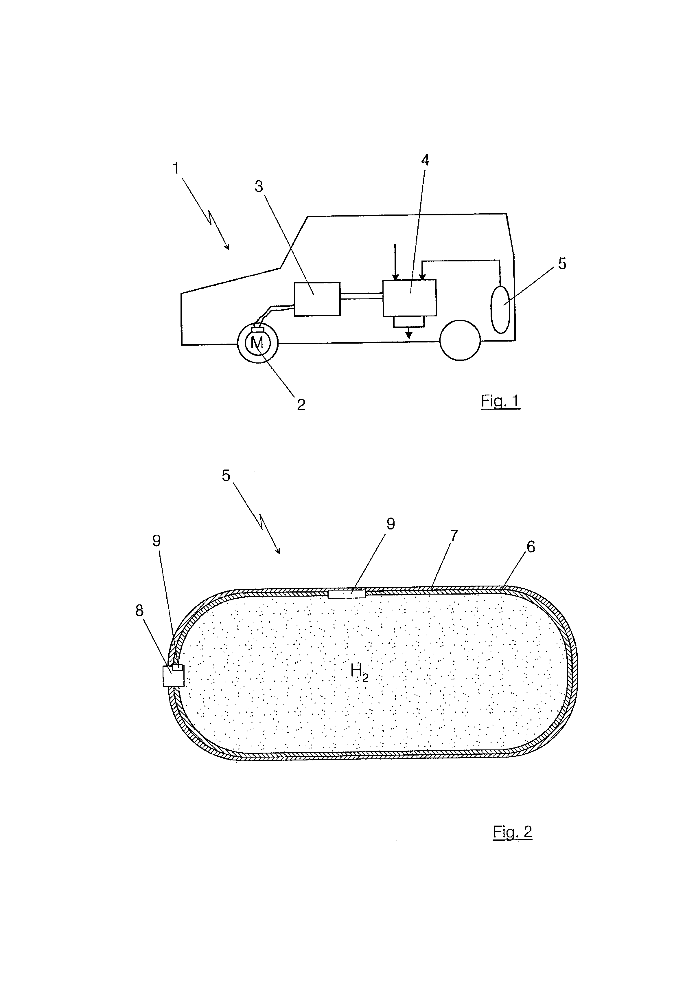
[0024]FIG. 1 illustrates a vehicle 1, which is principally driven by means of an electric motor 2 indicated in the region of the wheels, whereby this electric motor 2 is supplied via an electronic power unit 3 with electrical power from a fuel cell 4 in a manner known in itself. The electronic power unit 3 can thereby further comprise an electric intermediate storage element, for example a battery. The intermediate storage element can be used in particular to receive recovered brake energy. Oxygen or air and hydrogen H2 are fed to the fuel cell 4 in a known manner in order to produce the electrical power. The hydrogen comes from one or more devices 5 arranged distributed around the vehicle 1 for storing hydrogen H2 under high pressure. The device or the compressed gas storage element 5 is typically operated at a pressure level of for example 350 or 700 bar and is supposed to be formed in the exemplary embodiment shown here as a so-called type IV compressed gas storage element 5.

[002...


PUM

PropertyMeasurementUnit
Pressureaaaaaaaaaa
Pressureaaaaaaaaaa
Expansion enthalpyaaaaaaaaaa

Abstract

A device that stores a low molecular gas, such as hydrogen (H2), under high pressure includes having an inner shell and at least one outer sleeve surrounding the inner shell. The region between the inner shell and the outer sleeve is connected via at least one valve with a backflow prevention capability to the region surrounded by the inner shell. The valve is thereby formed so that low molecular gas which has diffused through the inner shell can flow back into the inner shell when there are suitable pressure conditions.

Description

BACKGROUND AND SUMMARY OF THE INVENTION[0001]Exemplary embodiments of the present invention relate to a device for storing low molecular gases under high pressure.[0002]Devices for storing gases or compressed gas storage elements are generally known. Typically, such compressed gas storage elements are sub-divided into different types. For example, a so-called type II compressed gas storage element is a compressed gas storage element with an inner shell made of high strength steel and an outer sleeve surrounding the inner shell, the outer sleeve being composed, for example, of fiber reinforced material. A type III pressure storage element comprises an inner shell composed of aluminum and a type IV pressure storage element typically comprises an inner shell made of a plastic material, for example high density polyethylene (HDPE), which is surrounded by at least one outer sleeve composed of fiber-reinforced material.[0003]Such compressed gas storage elements serve as devices for storin...

Claims


Application Information

Patent Timeline
IPC IPC(8): F16K15/02
CPCF17C1/16Y02E60/321F17C2201/056F17C2203/0604F17C2203/0619F17C2203/066F17C2203/0663F17C2205/0335F17C2205/0391F17C2205/0397F17C2221/012F17C2223/0123F17C2223/036F17C2260/037F17C2270/0168F17C2270/0184F16K15/021F17C2201/0109Y10T137/3149Y02E60/32
Inventor FRANZEN, JENSFRIEDLMEIER, GERARDOKIOSCHIS, KAIZUR MEGEDE, DETLEF
Owner DAIMLER AG
Why Eureka
Eureka Blog
Learn More