Insulation resistance measurement circuit having self-test function without generating leakage current

a measurement circuit and self-testing technology, applied in the direction of electric devices, instruments, transportation and packaging, etc., can solve the problems of large restrictions in circuit design and breakdown of insulation

Active Publication Date: 2013-07-11
SK ON CO LTD
View PDF2 Cites 25 Cited by
  • Summary
  • Abstract
  • Description
  • Claims
  • Application Information

AI Technical Summary

Benefits of technology

[0015]The insulation resistance measurement circuit according to an embodiment of the present invention can obtain an effect that switching of first and second switches is controlled such that a leakage current may not be generated in measuring insulation resistance, and voltages output through first and second operational amplifiers are measured after...

Problems solved by technology

One of methods for measuring a leakage current between the high voltage battery and the hybrid vehicle is breaking down insulation and forcibly making a DC current flow, but this method is disadvantageous in that insulation is broken down while insulation resistan...

Method used


Image

  • Insulation resistance measurement circuit having self-test function without generating leakage current
  • Insulation resistance measurement circuit having self-test function without generating leakage current
  • Insulation resistance measurement circuit having self-test function without generating leakage current

Examples


Embodiment Construction

[0024]101: insulation resistance measurement battery

[0025]102: insulation resistance unit

[0026]103: first source resistance unit

[0027]104: second source resistance unit

[0028]105: first operational amplifier

[0029]106: second operational amplifier

[0030]107: first switch

[0031]108: second switch

[0032]109: third switch

[0033]110: fourth switch

[0034]112: first voltage source

[0035]113: second voltage source

BEST MODE FOR CARRYING OUT THE INVENTION

[0036]Hereinafter, the embodiments of the present invention will be described in detail with reference to accompanying drawings.

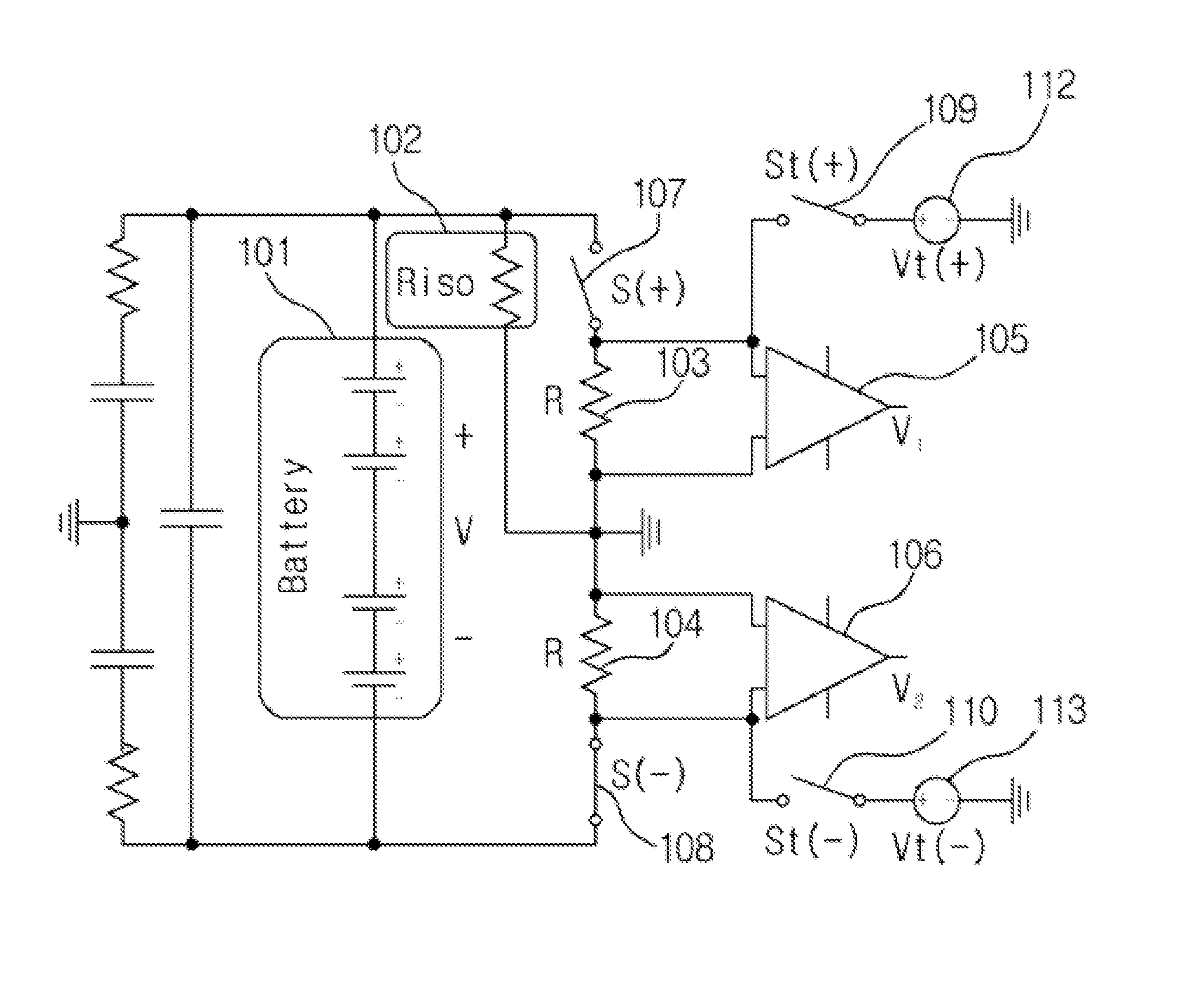
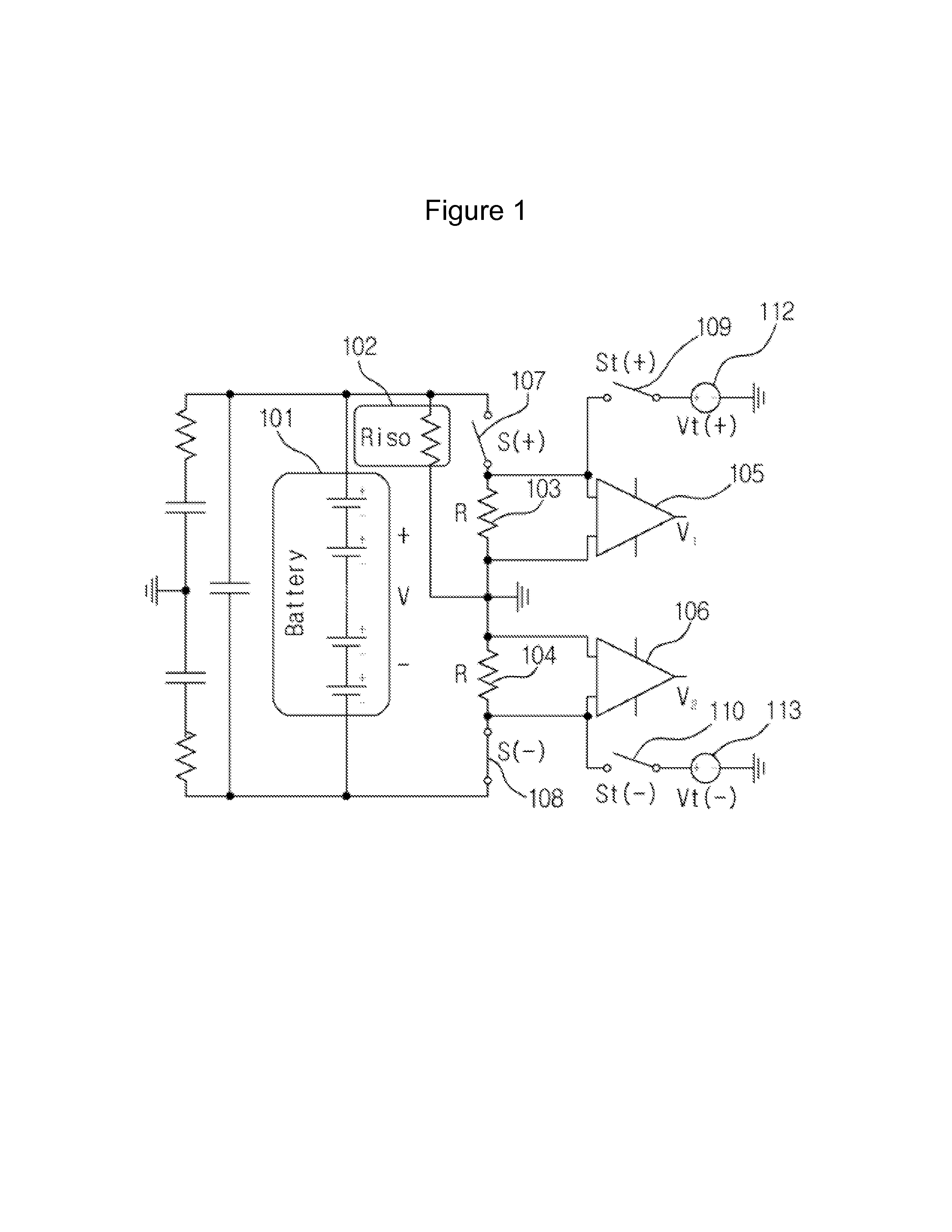
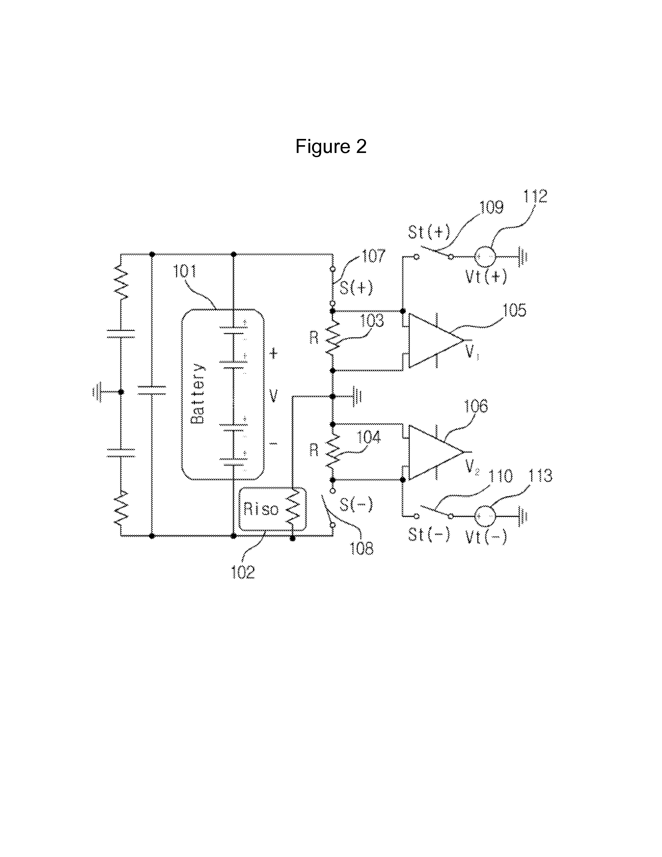
[0037]FIGS. 1 to 3 are circuit diagrams showing the configuration of an insulation resistance measurement circuit according to an embodiment of the present invention.

[0038]FIG. 1 is a circuit diagram showing a connection of an insulation resistance measurement circuit when a positive electrode of an insulation resistance measurement battery is broken down according to an embodiment of the present invention. FIG. 2 is a circ...


PUM


Abstract

Provided is an insulation resistance measurement circuit including: a source resistance unit including a first source resistance unit connected to a positive terminal of an insulation resistance measurement battery and a second source resistance unit connected to a negative terminal of the insulation resistance measurement battery and the first source resistance unit; a voltage sensing unit including a first operational amplifier sensing the voltage of the first source resistance unit, as a first voltage, and the voltage of the second source resistance unit, as a second voltage; a leakage current interrupting unit including a first switch connected to the positive terminal of the insulation resistance measurement battery and the first source resistance unit and a second switch connected to the negative terminal of the insulation resistance measurement battery and the second source resistance unit; a measurement circuit testing unit including a third switch connected to the first operational amplifier and a first voltage source and a fourth switch connected to the second operational amplifier and a second voltage source; and an insulation resistance measurement unit measuring insulation resistance of the insulation resistance measurement battery through the first and second voltages.

Description

TECHNICAL FIELD[0001]The present invention relates to an insulation resistance measurement circuit and, more particularly, to an insulation resistance measurement circuit in which switching of first and second switches is controlled such that a leakage current may not be generated in measuring insulation resistance, and voltages output through first and second operational amplifiers are measured after opening the first and second switches and closing third and fourth switches for self-testing of the insulation resistance measurement circuit.BACKGROUND ART[0002]A hybrid vehicle using a high voltage battery has a system for automatically cutting off power of the main high voltage battery in an emergency. The emergency refers to an excessive short circuit due to obsolescence of relevant components, an excessive short circuit caused by a short stemming from a breakdown of components due to a dielectric breakdown, etc., and an external impact, a dielectric breakdown, or the like.[0003]In...

Claims


Application Information

Patent Timeline
IPC IPC(8): G01R27/14
CPCB60L3/0069G01R27/14G01R31/025G01R27/025G01R35/00G01R31/52
Inventor YANG, JEONG HWAN
Owner SK ON CO LTD
Why Eureka
Try Eureka