
Dimensionally tolerant multiband conformal antenna arrays

a conformal antenna and multi-band technology, applied in the field of dimensionally tolerant highfrequency, multi-band conformal antenna arrays, can solve the problems of large size of low-frequency radio frequency (rf) signals such as hf, vhf and uhf, and significant affecting aircraft range, speed and maneuverability

Active Publication Date: 2013-07-11
LOCKHEED MARTIN CORP
View PDF6 Cites 18 Cited by
  • Summary
  • Abstract
  • Description
  • Claims
  • Application Information

AI Technical Summary

Benefits of technology

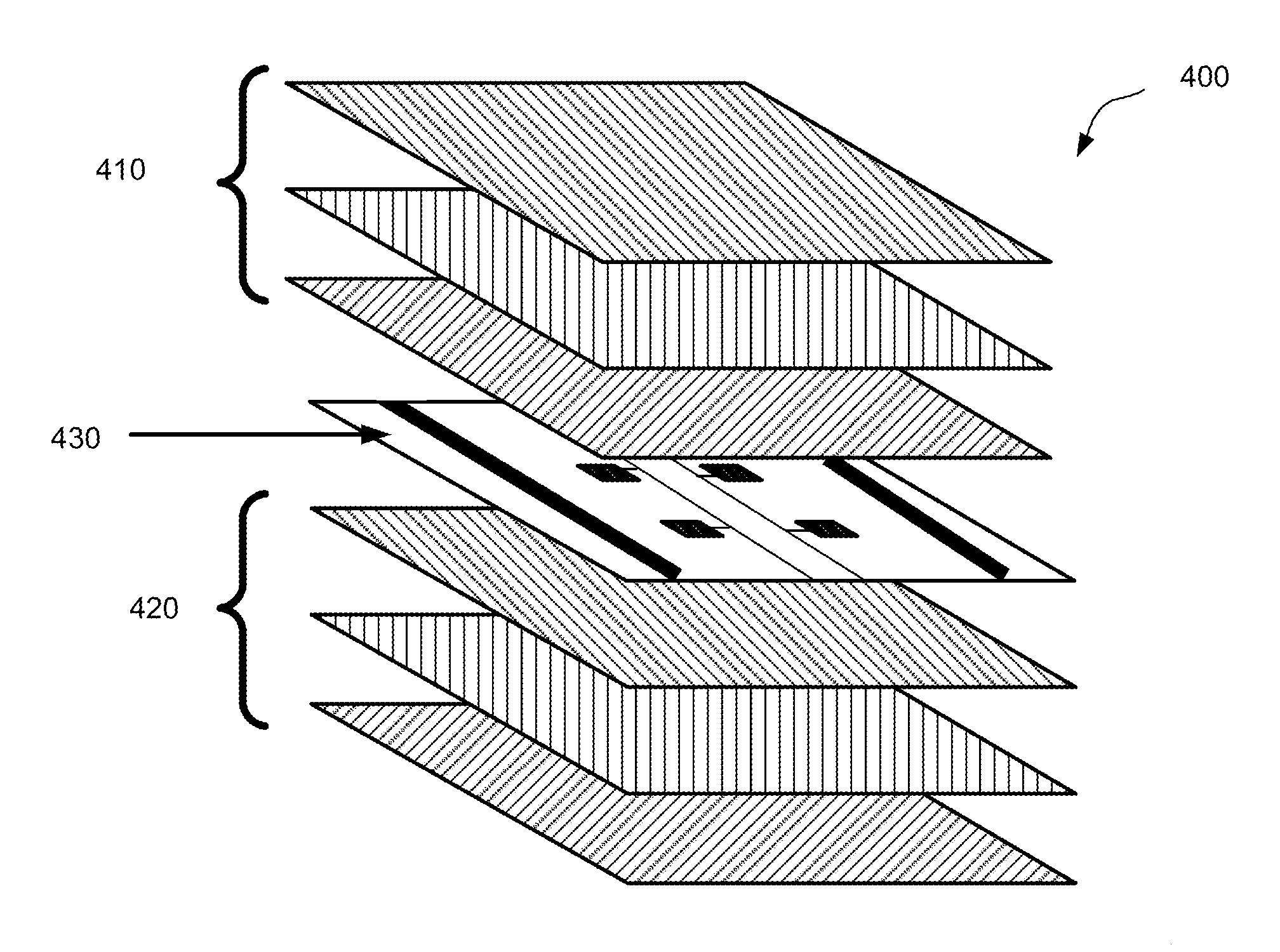
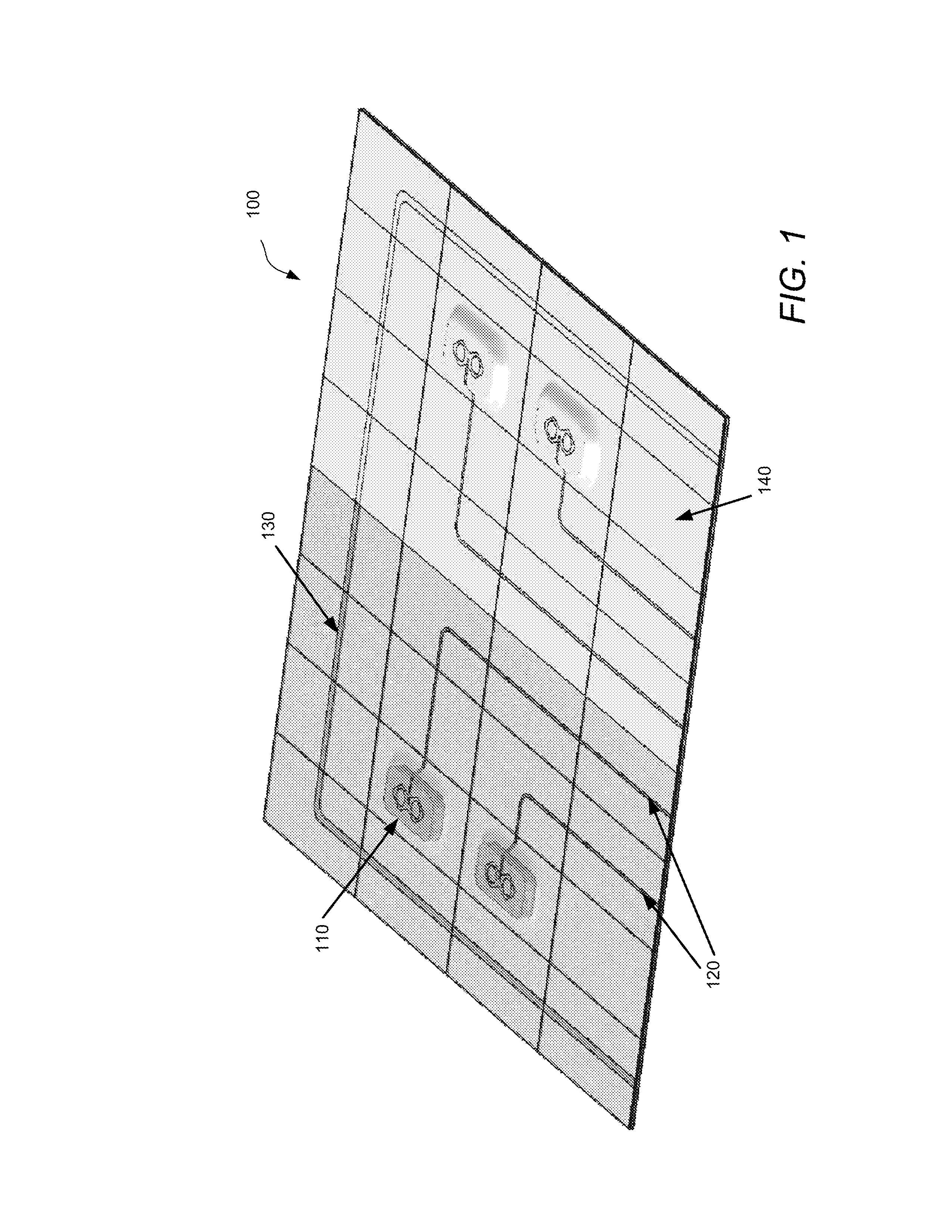
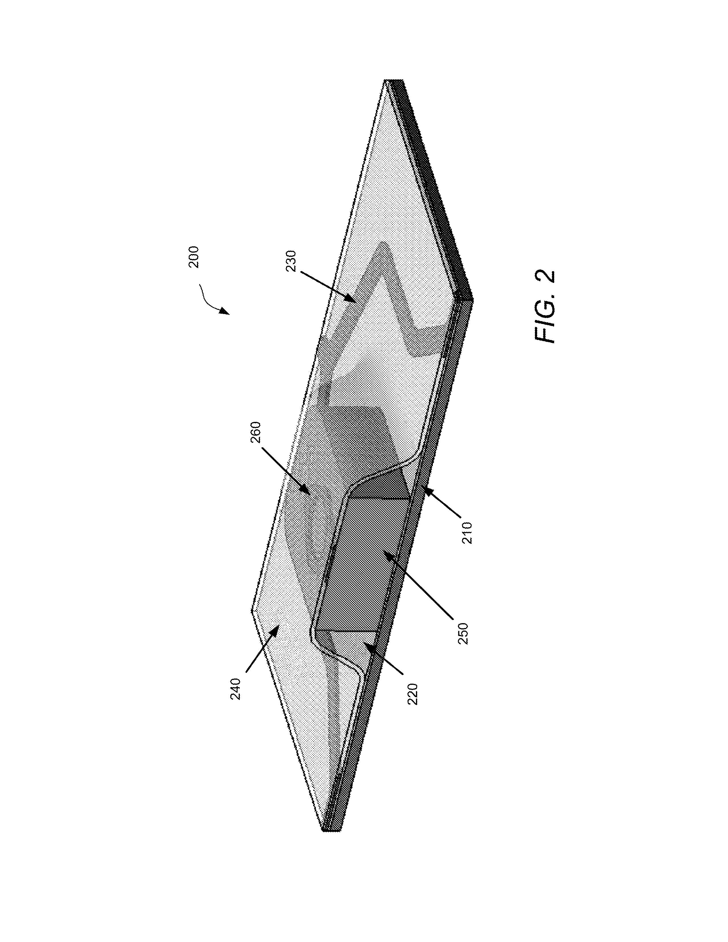
This patent describes a multiband antenna array that can be used in various applications such as vehicles. The array includes both high frequency and low frequency antenna elements. The low frequency elements are created using a flexible insulation layer made of nanoparticles applied to a flexible substrate using an inkjet nozzle or micropen dispenser. The antenna array can also be embedded within a composite material like fiber composite. The method involves applying nanoink onto a flexible substrate and heating the entire array with a low temperature oven to sinter the nanoink and create both the low frequency and high frequency antenna elements. Overall, this patent presents a flexible and tolerant antenna array that can be easily adapted and embedded in various materials.

Problems solved by technology

This may become problematic, especially in air vehicles such as unmanned air vehicles and helicopters, where the additional weight and drag from the retrofitted antennas may significantly affect aircraft range, speeds and maneuverability.
Further, the addition of, for example, blade antennas to the belly of the fuselage of an aircraft risk being damaged if the aircraft that may land on uneven surfaces.
Antennas that receive low frequency radio frequency (RF) signals, such as HF, VHF and UHF, are large in size because antenna performance is significantly degraded if the antenna size is not at least a quarter the size of the wavelength of the radiation.
Such large antennas are difficult to incorporate into combat vehicles for many of the same reasons listed above.
Further, large antennas that are constructed using rigid materials are more susceptible to damage than smaller antennas made from the same material.

Method used


Image

  • Dimensionally tolerant multiband conformal antenna arrays
  • Dimensionally tolerant multiband conformal antenna arrays
  • Dimensionally tolerant multiband conformal antenna arrays

Examples


Embodiment Construction

[0017]The inventors have recognized and appreciated that the size and weight of antennas may be significantly reduced by using nanoink technology, while simultaneously providing the ability to retrofit antennas onto vehicles with little to no impact on speed or maneuverability.

[0018]Nanoinks are a solution or paste of nanoparticles mixed with some “carrier solution” that controls the viscosity of the nanoink. The nanoink of some embodiments may be formulated in any suitable way and is not limited to any particular type. The carrier solution is not limited in any way, but may be, for example, optimized based on the method used to apply the nanoink. In some embodiments, the carrier solution may comprise a solvent. Any suitable solvent may be used; the invention is not limited in this respect. For example, the solvent may be water, an alcohol, a hydrocarbon fluid or some other organic fluid. The carrier solution may also comprise a dispersant to maintain the nanoparticles in suspension...


PUM

PropertyMeasurementUnit
Temperatureaaaaaaaaaa
Electrical conductivityaaaaaaaaaa
Flexibilityaaaaaaaaaa

Abstract

Some embodiments relate to a multiband antenna array formed on a flexible substrate. Low frequency antenna elements may be formed using nanoink. High frequency elements may be provided on a prefabricated antenna chip. The antenna array may be heated in a low temperature oven to sinter the nanoink into a solid antenna element. In some embodiments, an adhesive insulation layer may be provided which allows the antenna array to be attached to any surface. In other embodiments, the antenna array may be embedded in a composite material.

Description

BACKGROUND[0001]1. Technical Field[0002]The techniques described herein relate to dimensionally tolerant high-frequency, multiband conformal antenna arrays and a process for constructing such antenna arrays.[0003]2. Discussion of Related Art[0004]Modern combat vehicles, including air vehicles, water vehicles, and land vehicles, may utilize a wide variety of communications and electronic surveillance technologies. In the past, each different technology required a separate antenna, resulting in upwards of twenty antennas per vehicle. As technology progresses, new antennas may need to be installed, which requires retrofitting the new antennas onto vehicles that were not designed with the additional antennas in mind. This may become problematic, especially in air vehicles such as unmanned air vehicles and helicopters, where the additional weight and drag from the retrofitted antennas may significantly affect aircraft range, speeds and maneuverability. Further, the addition of, for examp...

Claims


Application Information

Patent Timeline
IPC IPC(8): H01Q1/38B32B38/14
CPCH01Q1/38H01Q21/28H01Q1/287B32B37/12B32B2457/00
Inventor VOS, DAVID L.BALDWIN, CARLDARLING, DAVID R.KAPLUN, BRIANDOROUGH, DAVID R.
Owner LOCKHEED MARTIN CORP
Learn More