Ccd accumulating charges outside the image frame

a technology of accumulating charges and images, applied in the field of ccd acc, can solve the problems of low dynamic range, low noise high dynamic range images in scientific and professional photography, small pixels with small full well capacity, etc., and achieve the effect of decoupling pixel size, high dynamic range, and low nois

Inactive Publication Date: 2013-07-11
GEORGIEV TODOR +1
View PDF0 Cites 2 Cited by
  • Summary
  • Abstract
  • Description
  • Claims
  • Application Information

AI Technical Summary

Benefits of technology

[0013]It is therefore a principal object of the present invention to provide embodiments of a CCD with small pixels which at the same time have significantly higher dynamic range and low noise. In other words, the goal is to decouple pixel size from noise and dynamic range.

Problems solved by technology

This results in low noise high dynamic range images in scientific and professional photography.
Unfortunately, in all prior art applications, pixel size is directly related to dynamic range and signal to noise ratio.
However, small pixels have small full well capacity.
This results in low dynamic range, and low signal to noise ratio.
Also the signal to noise ratio is totally unacceptable.
In the best case of strong illumination it is 30 times worse than with high end cameras, and at low illumination the noise is higher than the signal.
Also, taking multiple pictures is slow and there is a limit of how many pictures can be taken within a given total exposure time.
In this way, pixel size is coupled to dynamic range and to noise level.
Imaging with pixels of size under one micron is practically useless even if such pixels can be manufactured and are completely functional.
On the other hand, this is the range where optical microscopy also begins to fail due to diffraction.
This results in accumulation of charges from two or more pixels in the same pixel of the horizontal shift register.

Method used


Image

  • Ccd accumulating charges outside the image frame
  • Ccd accumulating charges outside the image frame
  • Ccd accumulating charges outside the image frame

Examples


first embodiment

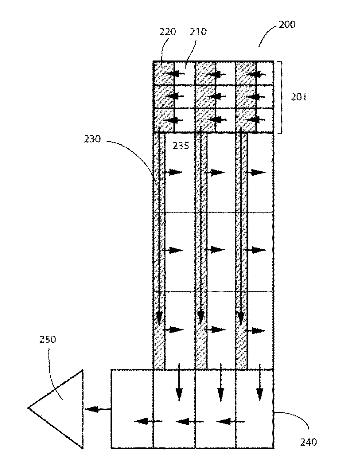
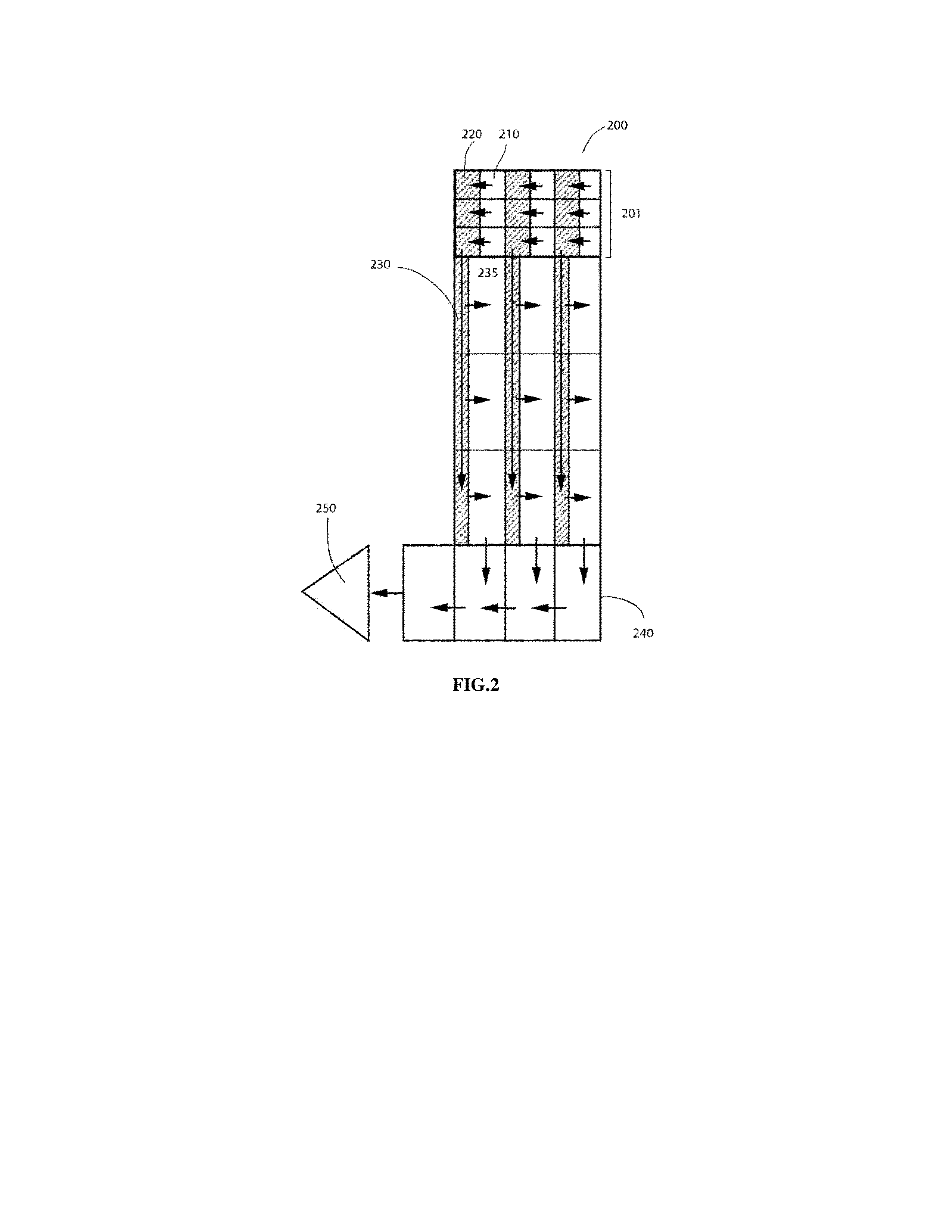
[0025]The first embodiment of this invention is based on modifications made to the prior art Frame Interline Transfer CCD described above. Referring to FIG. 2, the basic structure and functionality of the first embodiment 200 is shown. The image capturing frame 201 consists of two types of pixels: Light sensitive pixels (photodiodes) 210, and shielded pixels 220. Shielded pixels have the same charge holding capacity as the photodiodes. Shielded pixels are arranged into columns that will be called vertical shift registers. Immediately below the image capturing frame 201 there is a shielded storage frame comprising the same number of pixels as in 201. The structure of said frame is conceptually a duplicate of 201, only photodiodes are replaced with pixels capable of storing larger amounts of charge. Those pixels are called complementary pixels. Typically, a way to increase storage capacity of a pixel is by making the pixel bigger. One of the complementary pixels is represented as 235....

second embodiment

[0033]Referring to FIG. 3, the second embodiment of this invention is a CCD represented in two different phases of operation, 300a and 300b. This CCD is useful when the observed object changes slowly. The structure of this CCD is the same as in the first embodiment, except for the shielded storage frame, in which the complementary registers and the transfer of charges is implemented differently. The way in which the transfer of charges is realized in the shielded storage frame of this CCD allows that with a storage frame of the same size as in FIG. 2, two times higher dynamic range is achieved compared to FIG. 2. This is accomplished essentially by making the complementary storage registers two times bigger and running the whole process two times, as will be described next.

[0034]Before image capturing is started, all pixels are reset to zero. The functioning of the second embodiment can be presented considering three main steps.

[0035]In the first step charges created in all photodio...

third embodiment

[0042]This embodiment is useful when the observed object changes slow. Referring to FIG. 4, the third embodiment of this invention is a CCD represented in two different phases of operation, 400a and 400b. The structure of this CCD is the same as in the first embodiment, except for the larger size of the complementary registers, and the implementation of the transfer of charges from the shielded vertical registers of the image frame to the striped vertical registers of the storage frame. The way the transfer of charges from the image frame to the storage frame is realized in this CCD allows that with a storage frame of the same size as in FIG. 2, twice as high dynamic range is achieved compared to the first embodiment in FIG. 2.

[0043]Before image capturing is started, all pixels are reset to zero. The functioning of the third embodiment can be presented considering three main steps.

[0044]In the first step charges created in all photodiodes are transferred individually to the shielded...


PUM


Abstract

In one embodiment charges from the photodiodes in a CCD are interline-transferred to a vertical shift register; then they are transferred vertically to a second image frame, where they are interline-transferred to storage pixels in the second frame. Repeating this process one or more times leads to accumulation of charge in the storage pixels having full well capacity bigger than the original photodiodes. In another embodiment, charges from a CCD in the horizontal readout register are selectively transferred through a gate into a second horizontal register. From the second horizontal register charges are shifted vertically into vertical shift registers and then transferred into the storage pixels having big full well capacity. During readout time, in both cases charges are transferred to a horizontal shift register for readout as in a conventional CCD. In a plurality of embodiments this device can be used instead of a CCD with big pixels or binning, with the advantage that the photodiodes may be physically smaller in size compared to the size needed for storage of the full charge that is accumulated. This invention greatly extends the dynamic range that can be achieved with small pixels.

Description

BACKGROUND OF THE INVENTION[0001]High end imagers based on charge coupled devices (CCDs) are widely used in scientific applications, including microscopy, astronomy, and others. They are also used in professional photography to capture low noise images with high dynamic range. What is common for these applications is the large full well capacity of a pixel in the CCD. This is made possible by the large size of the pixel, up to 24 microns on a side, which can hold up to a million electrons. At the same time, the noise level of the amplifier used to read out those pixels is on the order of 10 to 20 electrons. Examples can be found on the website of Kodak at http: / / www.kodak.com / ek / US / en / Image_Sens_Solutions / Products / Full_Frame_CCD.htm.[0002]The noise level in a CCD is a combination of Shot noise, which is square root of the number of electrons, dark noise, and amplifier noise. With strong illumination the signal to noise ratio is a large number, proportional to the square root of the ...

Claims


Application Information

Patent Timeline
Patent Type & Authority Applications(United States)
IPC IPC(8): H04N5/335
CPCH04N5/335H04N5/37213H04N5/355H04N5/347H04N25/46H04N25/57H04N25/713H04N25/00
Inventor GEORGIEV, TODORGEORGIEVA, ELKA
Owner GEORGIEV TODOR
Why Eureka
Try Eureka