Over-voltage protection device for resonant wireless power reception device and method for controlling the over-voltage protection device

a protection device and wireless power technology, applied in the field of wireless power transmission and reception technique, can solve the problems of over-voltage protection that is difficult to achieve, the size and capacity of the required zener diodes also increases, and the reception device may generate excess power beyond a normal value, etc., to achieve the effect of easy handling of high over-voltage, high efficiency and rapid handling

Active Publication Date: 2013-07-11
SAMSUNG ELECTRONICS CO LTD
View PDF3 Cites 60 Cited by
  • Summary
  • Abstract
  • Description
  • Claims
  • Application Information

AI Technical Summary

Benefits of technology

[0011]Accordingly, the present invention provides an over-voltage protection device for a resonant wireless power transmission device, which is suitable for adoption in equipments such as portable terminals by achieving rapid handling, having high efficiency, easily handling a high over-voltage, and reducing a mounting size, and a method for controlling the over-voltage protection device.

Problems solved by technology

In the wireless power transmission and reception technique, in case of abnormal conditions, such as incorrect placement of a reception device on a charging deck of a transmission device, the reception device is abnormal, or a metallic substance is placed on the charging deck, excessive power beyond a normal value may be generated in the reception device.
However, the Zener diode needs a preparation period corresponding to a time necessary for its operation, and in that preparation period, over-voltage protection is difficult to achieve.
Moreover, as the amount of power to be handled increases, the size and capacity of the required Zener diode also increases.
In this case, there may be significant restrictions on a mounting size.
Such restrictions make it difficult to include a corresponding wireless power reception device in a portion of an electronic device for which a size limitation is vital.

Method used


Image

  • Over-voltage protection device for resonant wireless power reception device and method for controlling the over-voltage protection device
  • Over-voltage protection device for resonant wireless power reception device and method for controlling the over-voltage protection device
  • Over-voltage protection device for resonant wireless power reception device and method for controlling the over-voltage protection device

Examples


Embodiment Construction

[0022]Hereinafter, embodiments of the present invention will be described in detail with reference to the accompanying drawings.

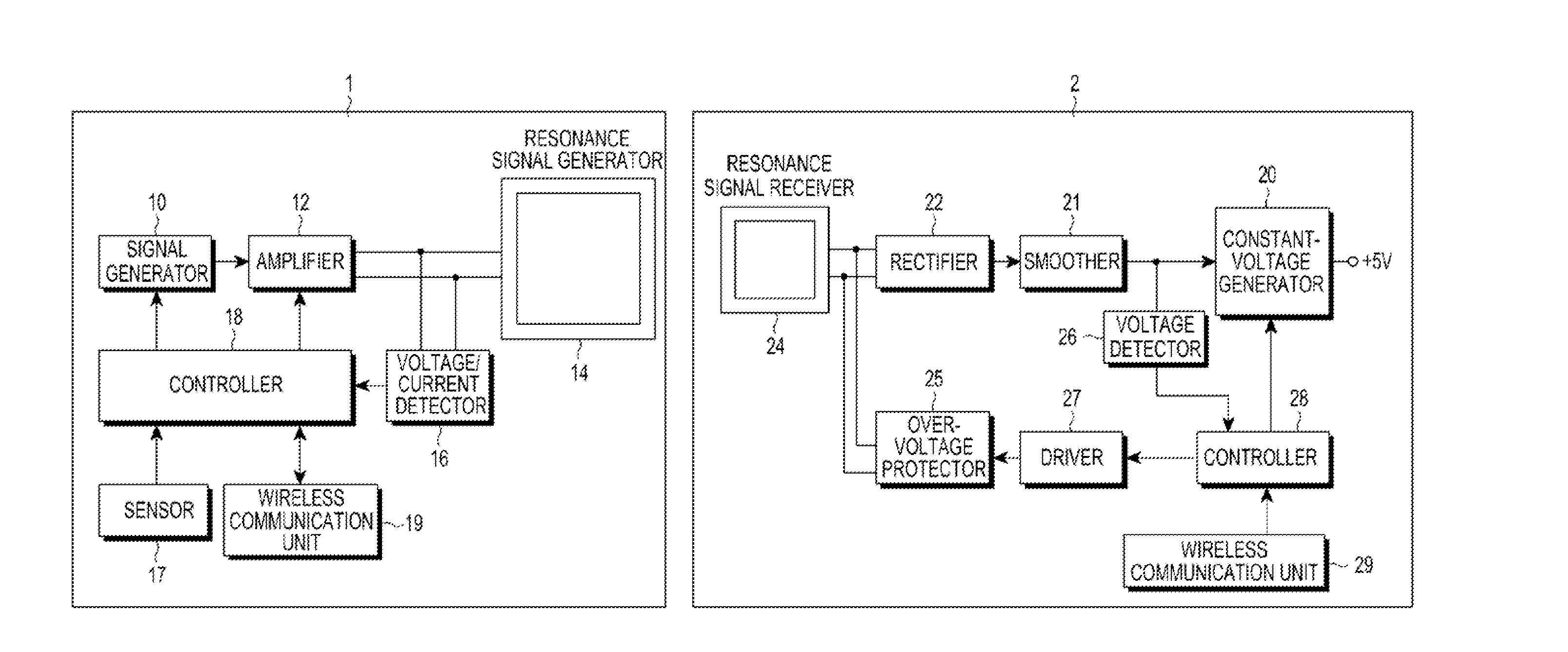
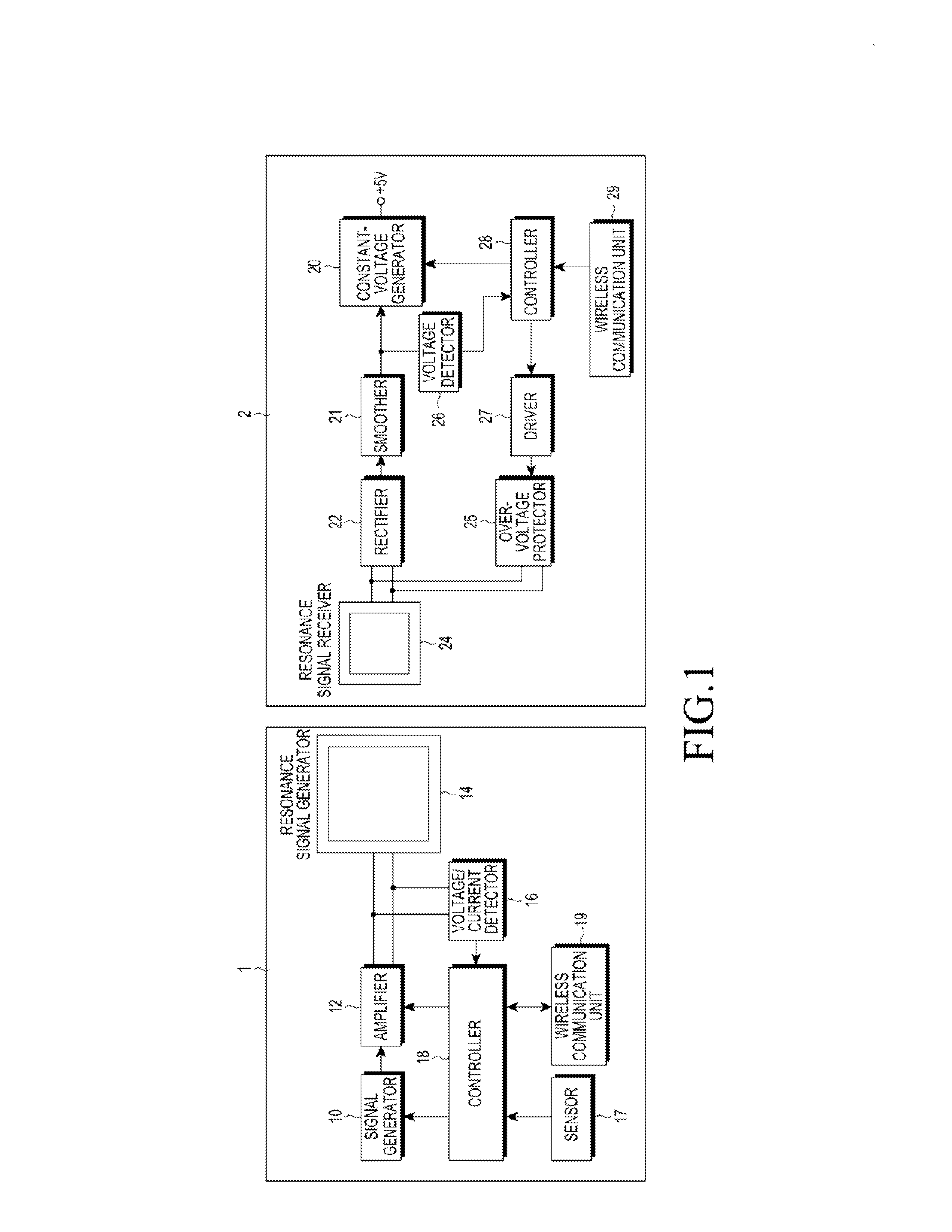
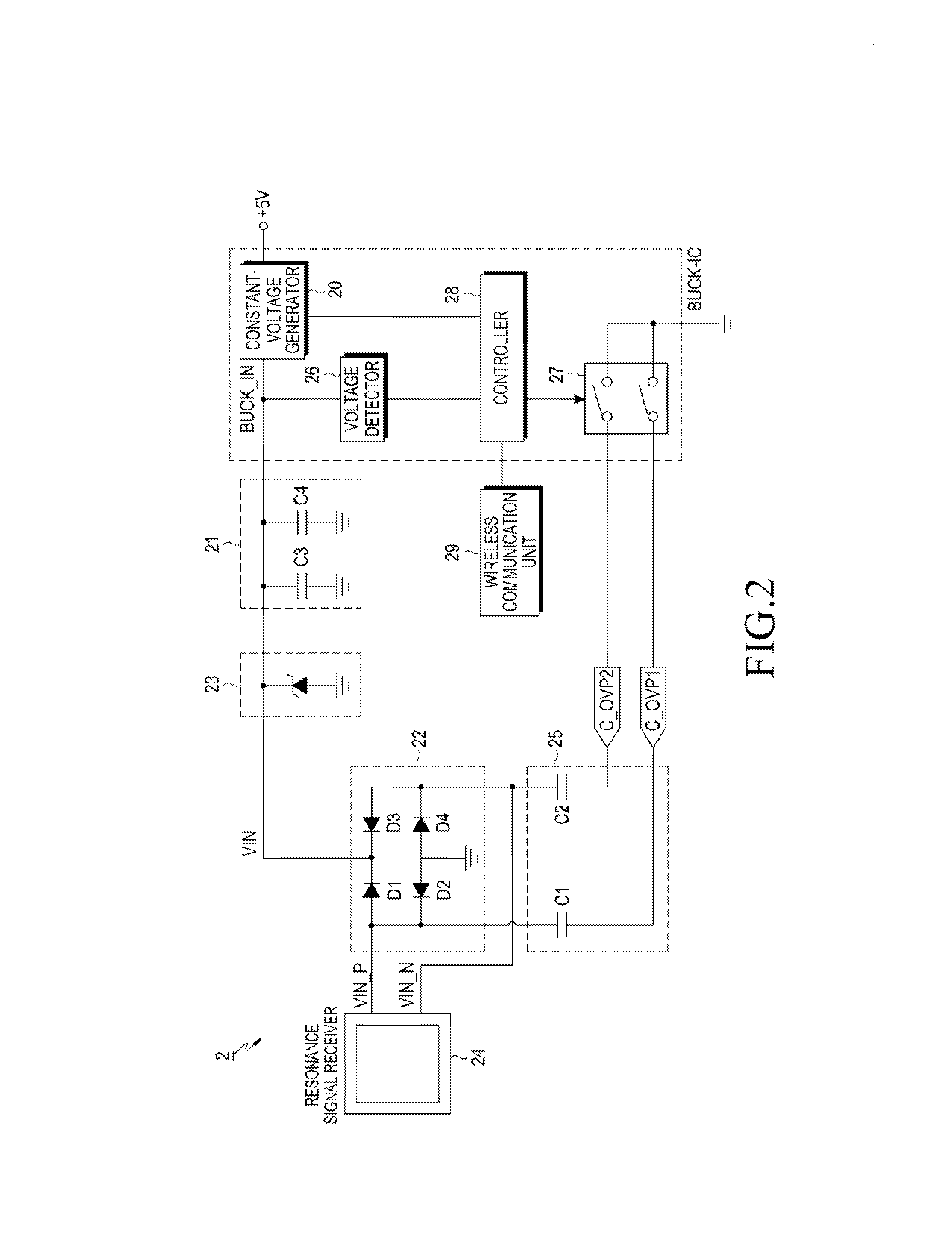
[0023]FIG. 1 illustrates a resonant wireless power transmission and reception system according to an embodiment of the present invention, and FIG. 2 illustrates a reception device of FIG. 1. Referring to FIGS. 1 and 2, the resonant wireless power transmission and reception system includes a wireless power transmission device 1, such as a charging device, and a wireless power reception device 2, such as one provided in a portable terminal.

[0024]The wireless power transmission device 1 may include a signal generator 10 which includes a Voltage Control Oscillator (VCO), to generate a signal of a preset frequency, such as a 6.78 MHz resonance frequency, an amplifier 12 which includes an amplification unit to amplify the signal generated by the signal generator 10 to a high-power signal, a resonance signal generator 14 which includes a resonator to generate a wi...


PUM


Abstract

Provided is an over-voltage protection device for a resonant wireless power reception device. The over-voltage protection device includes a resonance signal receiver for receiving a wireless resonance signal transmitted from a wireless power transmission device, an over-voltage protector which is driven by a driver in an over-voltage protection operation to detune a resonance frequency of the reception device, thereby reducing reception power, the driver for driving the over-voltage protector according to a control signal in the over-voltage protection operation, and a controller for outputting the control signal for driving the over-voltage protector to the driver when it is determined that over-voltage occurs.

Description

PRIORITY[0001]This application claims priority under 35 U.S.C. §119(a) to a Korean Patent Application filed in the Korean Intellectual Property Office on Jan. 11, 2012 and assigned Serial No. 10-2012-0003340, the contents of which are incorporated herein by reference.BACKGROUND OF THE INVENTION[0002]1. Field of the Invention[0003]The present invention relates generally to a wireless power transmission and reception technique applied to a wireless charging technique, and more particularly, to an over-voltage protection device for a reception device in a resonant wireless power transmission and reception technique and a method for controlling the over-voltage protection device.[0004]2. Description of the Related Art[0005]A wireless charging (or non-contact charging) technique, which uses a wireless power transmission and reception scheme, has recently been developed and used for various electronic devices. The wireless charging technique allows a user to automatically charge a battery...

Claims


Application Information

Patent Timeline
Patent Type & Authority Applications(United States)
IPC IPC(8): H02H9/04
CPCH02J7/025H02H9/04H02J5/005Y02B60/50H02H9/028H02H9/042H02J50/10H02J50/80H02J7/00034H02J50/12H02J7/00308H02J50/90
Inventor KIM, YU-SUKIM, JOON-ILPARK, SE-HOPARK, SUNG-KWEON
Owner SAMSUNG ELECTRONICS CO LTD
Why Eureka
Try Eureka