Static Electricity Dissipation Drain and Standoffs for By-Pass Conductors of Floating Roof Tanks

Inactive Publication Date: 2013-07-11
LIGHTNING MASTER CORP
View PDF5 Cites 8 Cited by
  • Summary
  • Abstract
  • Description
  • Claims
  • Application Information

AI Technical Summary

Benefits of technology

[0035](1) A static charge is created by normal tank operations (filling and emptying). Moving a stream of liquid through standing liquid strips ions, thereby creating a charge. Also, secondary effect from a direct or nearby lightning strike has the same effect. There is little that can be done to mitigate this condition.
[0036](2) Charge dissipates from the liquid in the tank onto points and edges. Even if the liquid is in a steel tank, the charge cannot dissipate into the steel, but must inductively couple. That takes time, allowing the charge to build more quickly th

Problems solved by technology

There is little that can be do

Method used


Image

  • Static Electricity Dissipation Drain and Standoffs for By-Pass Conductors of Floating Roof Tanks
  • Static Electricity Dissipation Drain and Standoffs for By-Pass Conductors of Floating Roof Tanks
  • Static Electricity Dissipation Drain and Standoffs for By-Pass Conductors of Floating Roof Tanks

Examples


Embodiment Construction

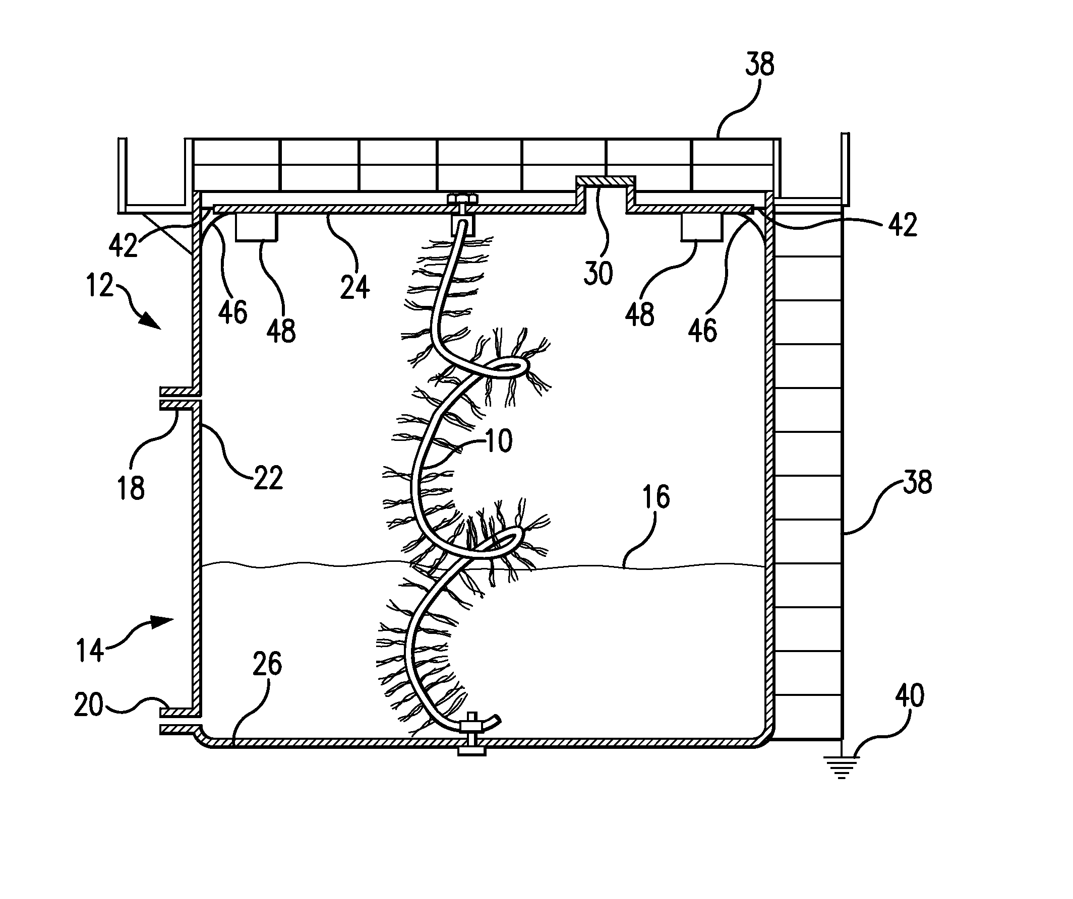
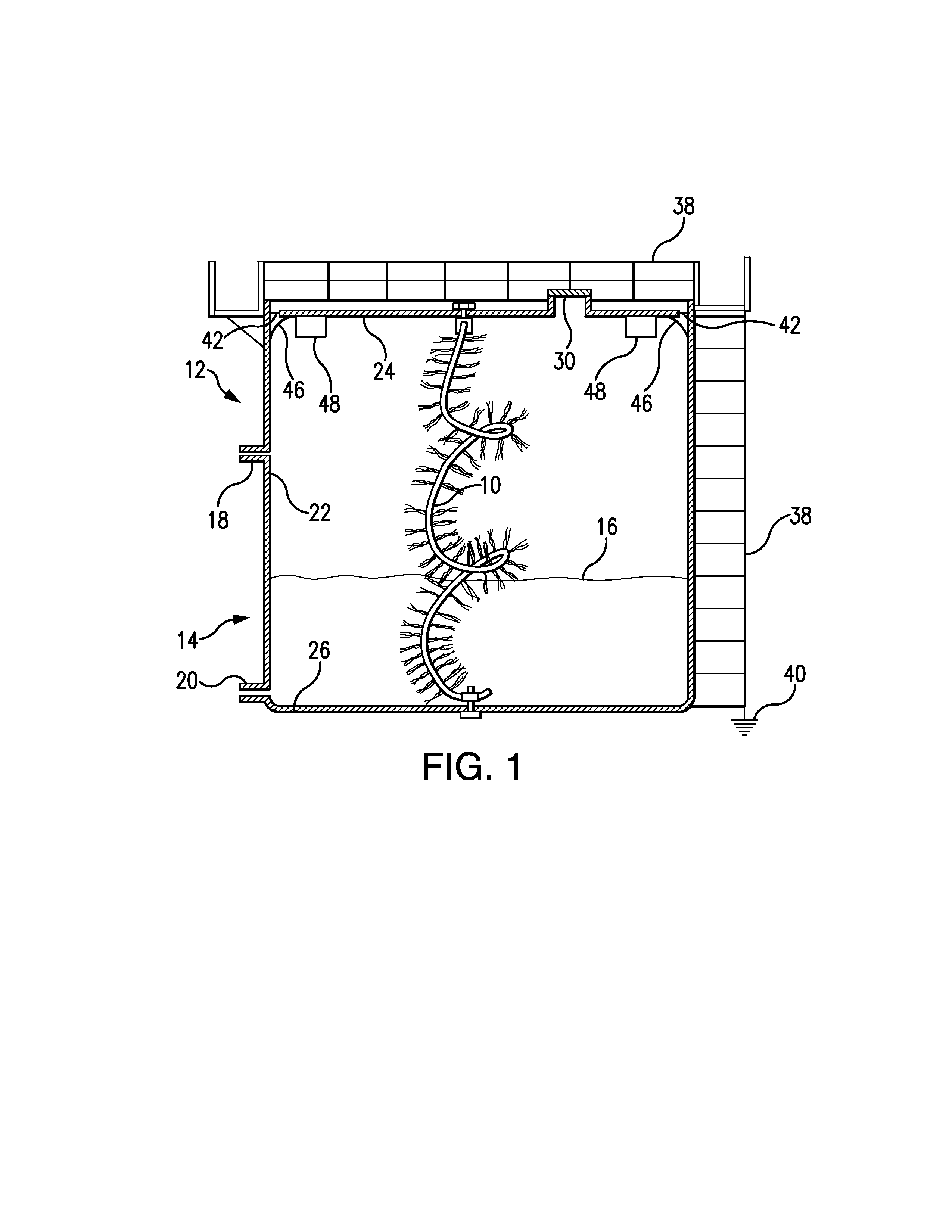
[0068]Referring to FIG. 1, the static electricity dissipator drain 10 of the invention is intended to be installed within a structure 12 such as a storage tank 14 to dissipate the build-up of static electricity within the tank 14 as the product is filled with product 16 via inlet 18 or emptied via outlet 20.

[0069]More particularly, conventional storage tanks 14 comprise a generally cylindrical configuration composed of a side wall 22 covered by a top wall 24 and supported by a bottom wall 26. In some storage tanks 14, the top wall 24 is fixed whereas in other storage tanks 14, the top wall 24 floats upon the fluid product 16 to move upwardly upon filling the tank via inlet 18 or to slide downwardly upon emptying the tank via outlet 20.

[0070]Without departing from the spirit and scope of the invention, the tank 14 may alternatively comprise barges and ships that have internal tanks for the storage of flammable or explosive material.

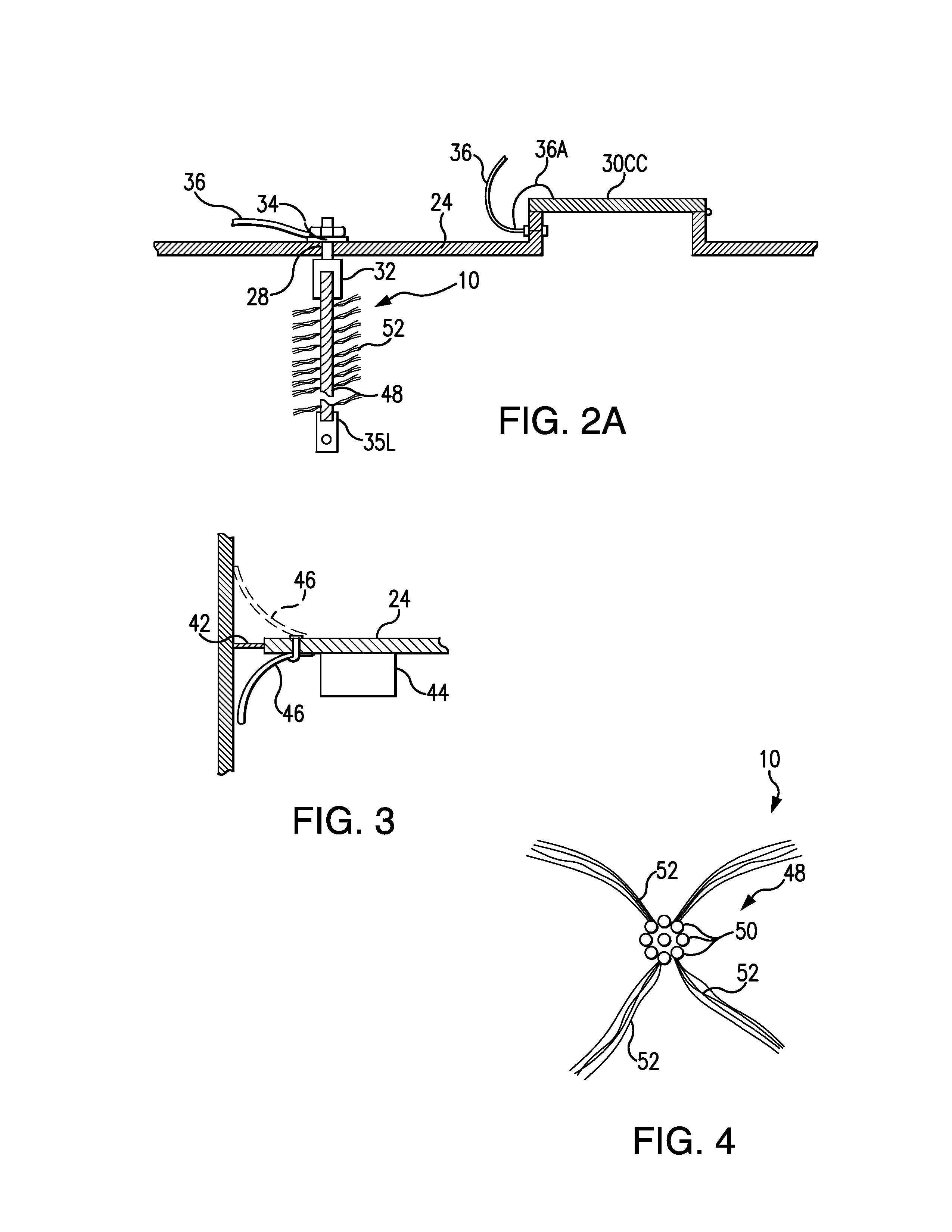
[0071]The standing end of the static electricity dis...


PUM

PropertyMeasurementUnit
Flexibilityaaaaaaaaaa
Radiusaaaaaaaaaa
Fouling propertiesaaaaaaaaaa

Abstract

A bonding system for a tank battery containing a flammable or combustible product being stored or conveyed, including a bonding conductor, an electrically conductive base member mounted on the tank, the electrically-conductive base member electrically connected to the bonding conductor and to ground installed within each tank and also including a flexible conductive medium with an upper end and a lower end and a plurality of fine electrically-conductive metal wires each having a proximal end and a terminal end, the proximal ends of which are intertwined with the flexible conductive medium to be in electrical connection with the electrical conductive medium, the upper end of the flexible conductive medium electrically connected with the electrically conductive base member and a plurality of static drains located proximate to the highest points of the tank battery and electrically bonded to said bonding conductor.

Description

CROSS REFERENCE TO RELATED APPLICATIONS[0001]This application claims the benefit of provisional patent application Ser. No. 61 / 550001 filed Oct. 21, 2011 and 61 / 684857 filed Aug. 20, 2012, the disclosures of each of which are hereby incorporated by reference herein.BACKGROUND OF THE INVENTION[0002]1. Field of the Invention[0003]This invention relates to static electricity dissipation drains for dissipating static charges within structures such as storage tanks to minimize a build-up of static electrical potential within the structure that might create an electrical spark within the storage tank.[0004]2. Description of the Background Art[0005]As set forth in my prior patent, U.S. Pat. No. 4,910,636, the disclosure of which is hereby incorporated by reference herein, static electricity dissipators have been used to dissipate electrical charges during a thunderstorm to thereby minimize the likelihood of a lightning strike that might otherwise occur due to the electrical potential betwe...

Claims


Application Information

Patent Timeline
IPC IPC(8): H05F1/00H01R43/26
CPCB65D90/46H05F1/00Y10T29/49117H01R3/08H01R4/64H01R43/26
Inventor KAISSER, BRUCE A.OLDHAM, JAMES R.BATTLE, JOHN R.
Owner LIGHTNING MASTER CORP
Why Eureka
Try Eureka