Segmented spotlight having narrow beam size and high lumen output

Inactive Publication Date: 2013-07-11
KONINKLIJKE PHILIPS ELECTRONICS NV
View PDF7 Cites 6 Cited by
  • Summary
  • Abstract
  • Description
  • Claims
  • Application Information

AI Technical Summary

Benefits of technology

[0013]Embodiment of claim 8 provides that the optical module may further include a light transmitting layer adapted to transmit light diffusively and arranged to cover at least a portion of the light-entry surface of the light guide. The light transmitting layer allows for controlled and efficient incoupling of diffuse light transmitted from a comparatively large area into the light guide. Dimensioning of the light guide allows for forming the incoupled light into a light beam having predetermined properties when leaving the light guide, which properties allow for fulfillment of luminaire requirements, e.g. as regards to angular distribution and glare. The light transmitting layer may be a light transmissive layer adapted to diffuse incident light and output the diffused light from the side of the layer facing the light-entry surface. Hence, problems related to light source brightness can be remedied or alleviated without using a diffuser at the luminaire output.
[0014]Embodiment of claim 9 provides that the light transmitting layer may also be a light emitting layer adapted to emit light in response to excitation. The light emitting layer may thus be a layer that can generate light and not a translucent layer that merely forwards light through the layer. The light emitting layer may be a layer adapted to emit light in response to excitation by light, preferably a phosphor layer. It has been found that increased efficiency is particularly desirable/needed in slim luminaires (large light output area compared to thickness) from which a uniform and “non-glare” light is desirable to provide. In such luminaires the active phosphor area for re-generating the light will be relatively small compared to the to

Problems solved by technology

One drawback of the proposed structure is that increasing the size of the source cavity also increases the beamwidth of the output light. FIG. 1 illustrates a relationship between the diameter of the source cavity and the bea

Method used


Image

  • Segmented spotlight having narrow beam size and high lumen output
  • Segmented spotlight having narrow beam size and high lumen output
  • Segmented spotlight having narrow beam size and high lumen output

Examples


Embodiment Construction

[0028]In the following description, numerous specific details are set forth to provide a more thorough understanding of the present invention. However, it will be apparent to one of skill in the art that the present invention may be practiced without one or more of these specific details. In other instances, well-known features have not been described in order to avoid obscuring the present invention.

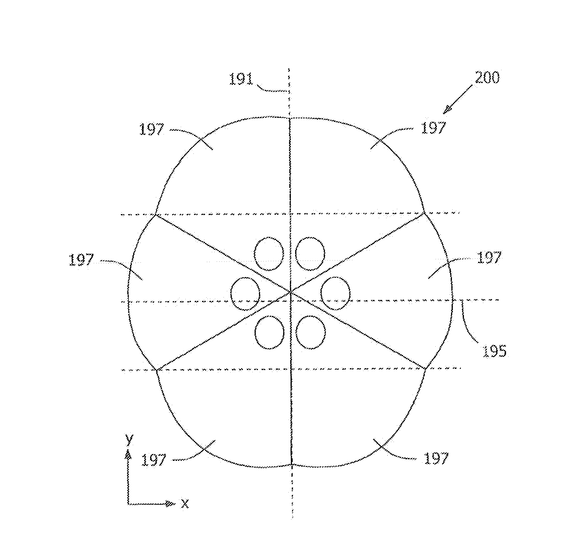
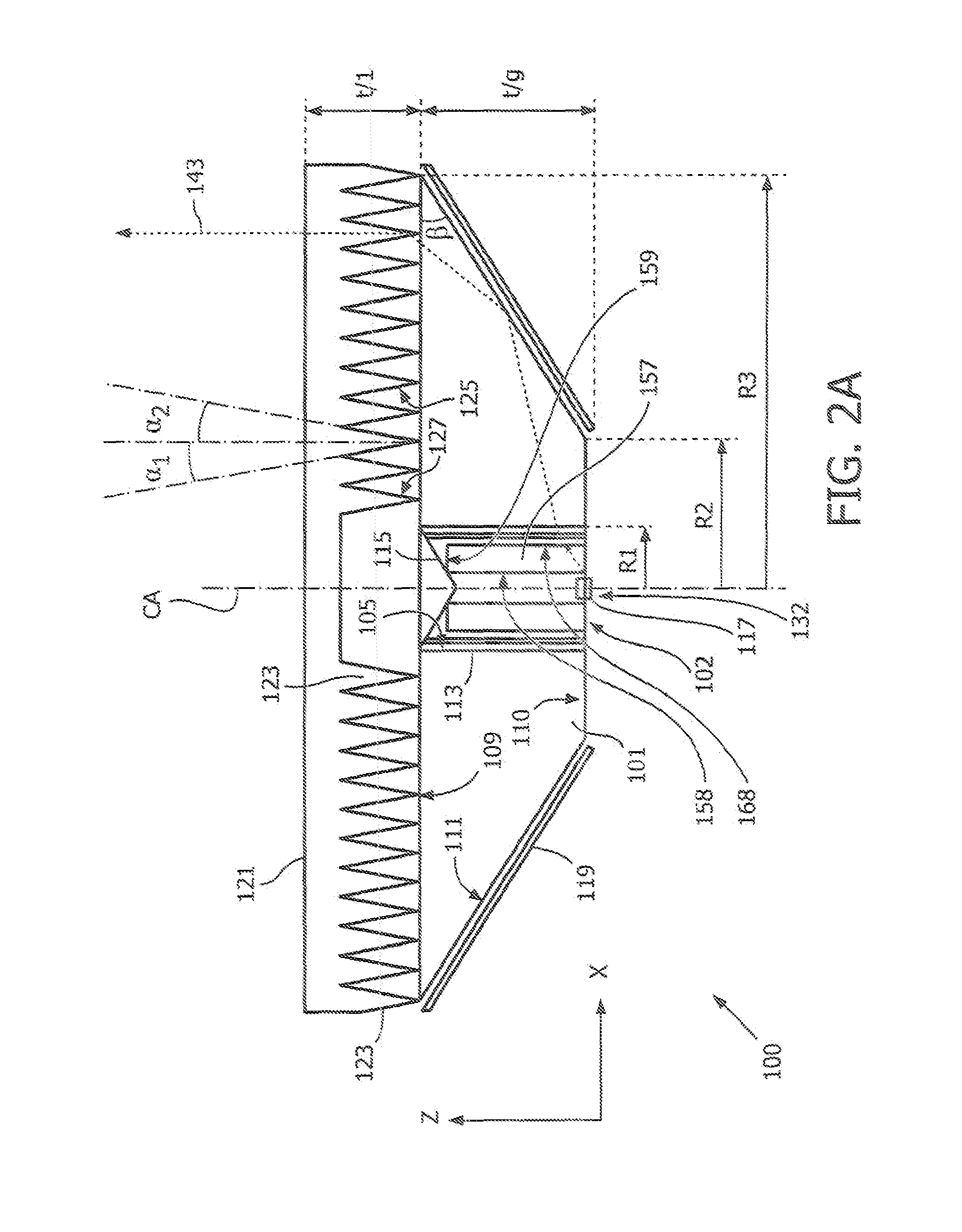
[0029]FIGS. 2A-2B show a cross-sectional side view and a top view of a luminaire arrangement 100, a pie-shaped section of which may be used in an optical module according to an embodiment of the present invention. The shown luminaire arrangement comprises a light guide 101, here circle symmetric in a plane y-x. The light guide 101 has a cylindrical through-hole 102, which inner side is a light-entry surface 105 covered by a light emitting layer 113, here a layer that emits light upon illumination, preferably a phosphor layer. The light emitting layer 113 is not in direct contact with th...


PUM


Abstract

The invention relates to an optical module comprising two or more segments positioned around an axis of symmetry of the module. Each segment includes a light collimating structure for providing a predefined light distribution of light exiting the module and a light source assembled in a cavity within the light collimating structure. The center of the cavity coincides with the optical axis of the light collimating structure and is at a distance (d) from the axis of symmetry of the module. Including two or more segments where each segment comprises its own light source allows obtaining higher lumen output compared to prior art luminaires having only one light source while arranging the segments so that the center of each cavity coincides with the optical axis of the collimating structure of the segment allows preserving narrow beamwidth collimation of the light exiting the module.

Description

FIELD OF THE INVENTION[0001]Embodiments of the present invention relate generally to the field of illumination systems, and, more specifically, to optical modules for providing light output having narrow beam size and high lumen output.BACKGROUND OF THE INVENTION[0002]As the efficacy (measured in lumens per Watt) of light emitting diodes (LEDs) increases and prices go down, it is expected that LED illumination and LED based luminaires soon will be serious alternatives to and at a competitive level with until now predominant tube luminescent (TL) based luminaires.[0003]WO 2008 / 126023 describes a luminaire comprising a light source positioned within a source cavity in a collimating structure arranged for providing predefined light distribution from the luminaire. The light source includes a plurality of LEDS. The number of LEDS that can be included within the source cavity depends on the size of the cavity. In turn, the intensity of the light produced by the luminaire depends on the n...

Claims


Application Information

Patent Timeline
IPC IPC(8): F21V7/00F21V13/02
CPCF21K9/00F21K9/52F21Y2101/02F21Y2113/002G02B6/0053F21V13/02G02B6/0078H01L33/58F21V7/00F21V7/0033G02B6/0073F21K9/61F21K9/64F21Y2113/10F21Y2115/10
Inventor DESMET, LIEVEN RAF ROGERBELIK, OLEG
Owner KONINKLIJKE PHILIPS ELECTRONICS NV
Why Eureka
Try Eureka