Power tool and operation method thereof

a technology of power tools and head assemblies, applied in the field of handclamped power tools, can solve the problems of wasting time and energy, affecting the operation efficiency of the power tool, and the head installation of the oscillating tool adopts a relatively out-of-date design, so as to avoid slippage of the head, ensure the installation, and fast assemble or disassemble the head

Inactive Publication Date: 2013-07-18
POSITEC POWER TOOLS (SUZHOU) CO LTD
View PDF2 Cites 30 Cited by
  • Summary
  • Abstract
  • Description
  • Claims
  • Application Information

AI Technical Summary

Benefits of technology

[0028]The advantage of the invention is: quickly drive the fastener and the locking member screwed or loosened to fast assemble or disassemble the head without any other auxiliary tools by the drive mechanism installed on the housing. Because of driving the fastener and the locking member screwed through rotating the driving mechanism several circles, it assure the axial press force on the head is high enough to reliably installing the head on the output shaft and avoid slippage of the head in any environments to improve the working efficiency.

Problems solved by technology

However, the existing oscillation tool still adopts a relatively out-date head installation means, which means that the locking member is installed on or taken down from the output after the fastening bolts are loosened with a wrench; likewise, the same way is adopted for installation and replacement of attachments, and the head is replaced, screwed, and installed by loosening the fastening bolts with the wrench.
The operation is very complicated and wastes time and energy.

Method used


Image

  • Power tool and operation method thereof
  • Power tool and operation method thereof
  • Power tool and operation method thereof

Examples


embodiment 1

[0044]The power tool described in this embodiment is an oscillating type power tool, also called an oscillation tool. However, the present invention is not limited to oscillating-type power tools, and also may be a rotary type grinding power tool, such as a sander or an angle grinder.

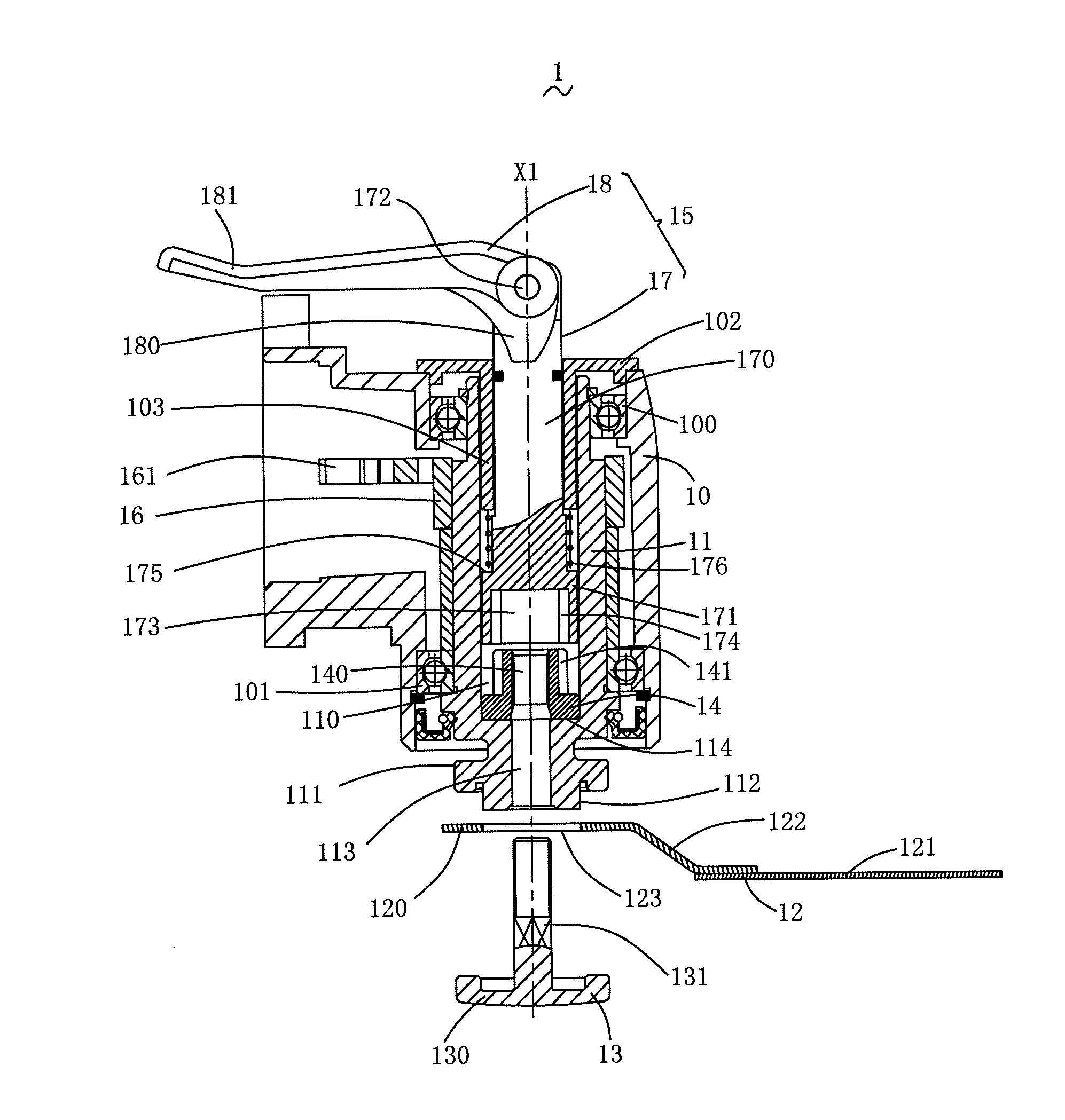
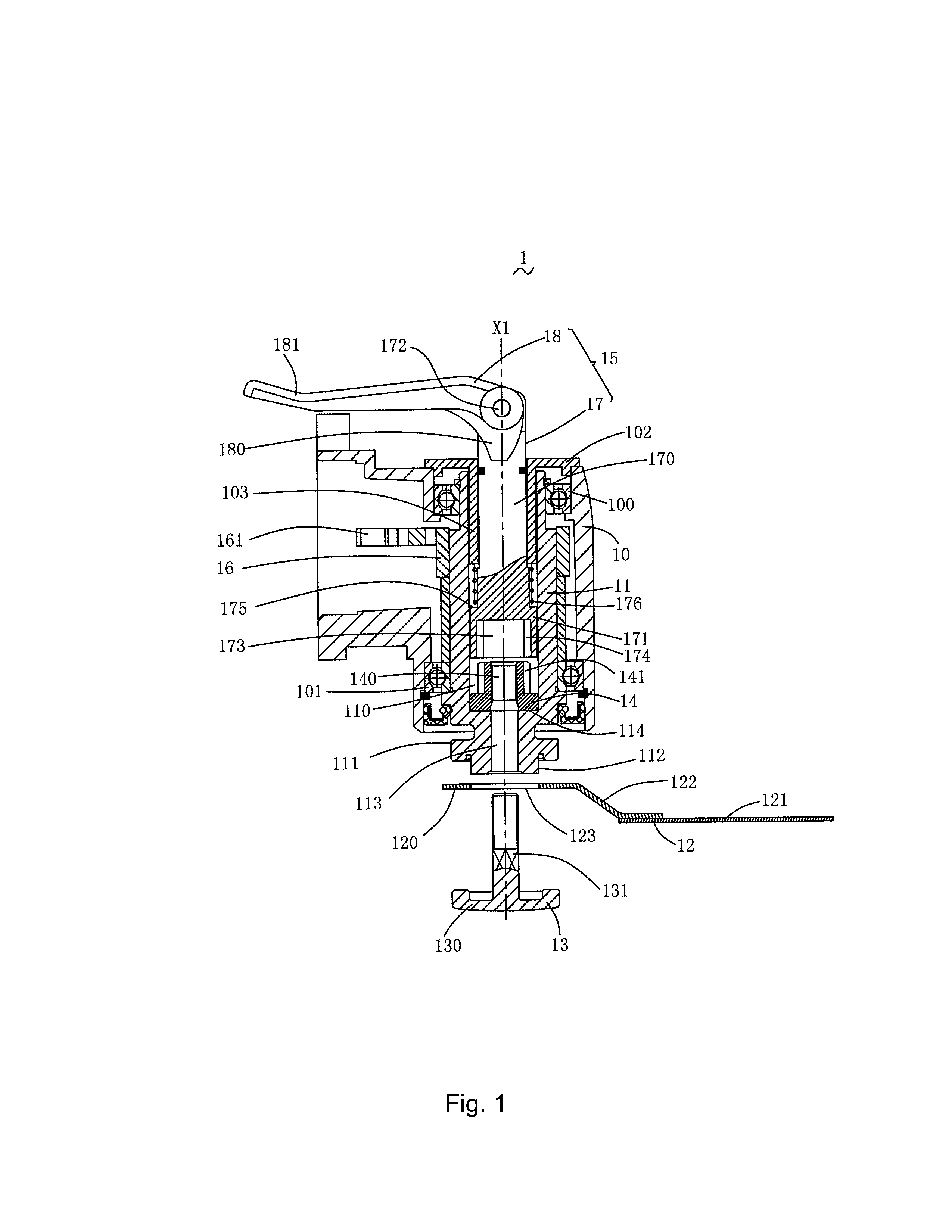
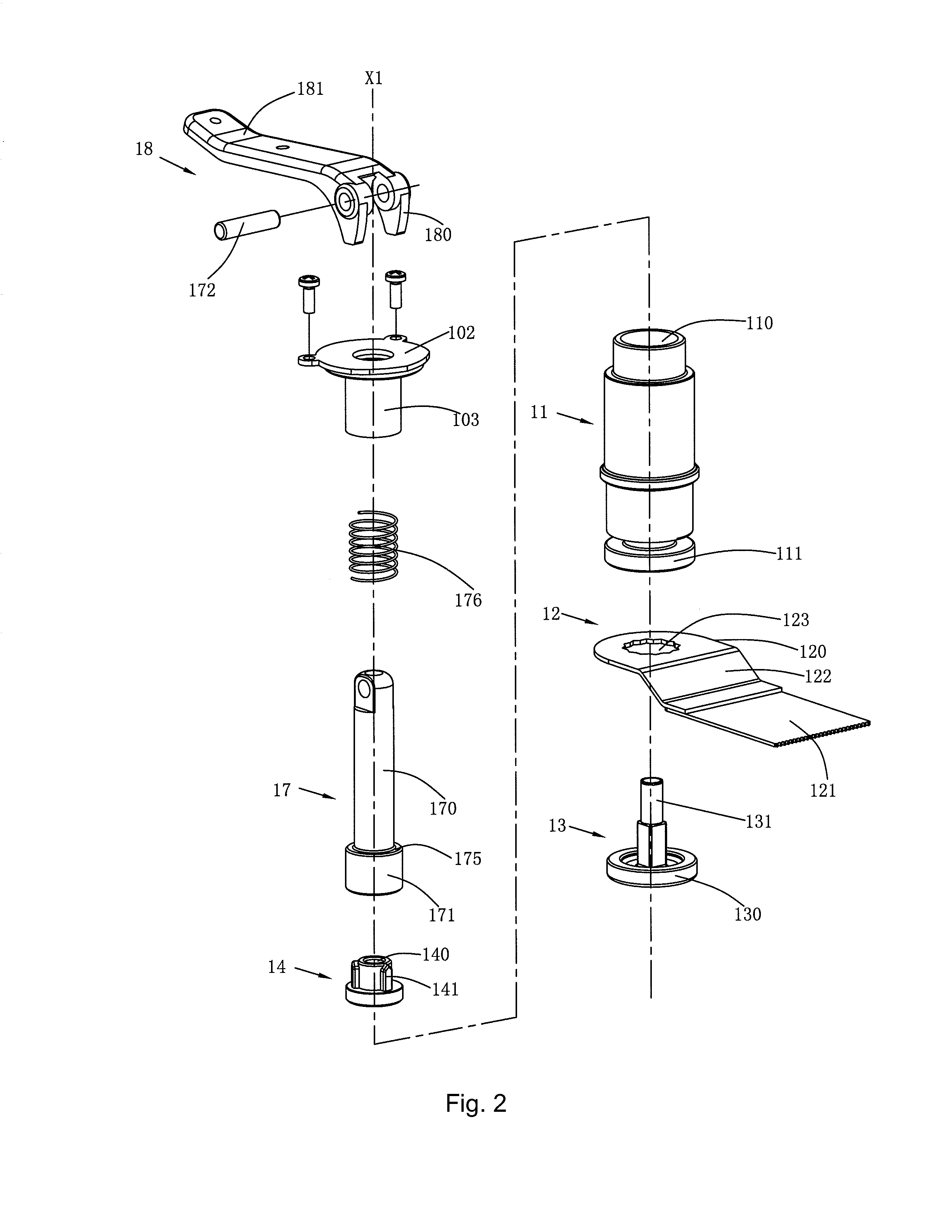
[0045]FIG. 1 illustrates the head area of the oscillation tool 1 in this embodiment. The oscillation tool 1 has a housing 10, an output shaft 11 extending out from the housing 10, a head 12 installed at the end of the output shaft 11, a locking member 13 for fixing the head 12 at the end of the output shaft 11, a fastener 14 supported in the output shaft 11, and a driving mechanism 15 capable of rotating around the axis X1 of the output shaft 11. When rotated along one direction, the driving mechanism 15 can drive the fastener 14 and the fastener 13 to be screwed; and when rotated along the opposite direction, the driving mechanism 15 can drive the fastener 14 and the locking member 13 to be loosened.

[0...

embodiment 2

[0072]As shown in FIGS. 7-10, the second embodiment of the present invention discloses an oscillating type power tool, namely an oscillation tool 2. The oscillation tool 2 comprises a housing 20, an output shaft 21 installed in the housing 20, a locking member 22 inserted into the output shaft 21, a head 23 clamped between the locking member 22 and the output shaft 21, a fastener 24 received in the output shaft 21 and used for locking the locking member 22, and a driving mechanism 25 for driving the fastener 24 to rotate around the axis X2 of the output shaft 21.

[0073]As shown in FIGS. 7 and 8, in comparison with the oscillation tool 1 in the first embodiment, the driving mechanism 25 has a different structure. The driving mechanism 25 specially comprises an operating assembly 26 and a driving assembly 27. The operating assembly 26 is operable to drive the driving assembly 27 to rotate. The operating assembly 26 comprises a cylindrical sleeve 260 installed on the top of the housing ...

embodiment 3

[0078]The following is a brief description of embodiment three of the present invention with reference to the FIG. 11. An oscillation tool 3 comprises a housing 30, an output shaft 31 installed in the housing 30, a locking member 32 inserted into the output shaft 31, a head 33 clamped between the locking member 32 and the output shaft 31, a fastener 34 received in the output shaft 31 and used for locking the locking member 32, and a driving mechanism 35 for driving the fastener 34 to rotate around the axis X3 of the output shaft 31. The driving mechanism 35 comprises an operating assembly 350 and a driving assembly 351. The operating assembly 350 is operable to drive the driving assembly 351 to rotate. The oscillation tool 3 in the second embodiment is different from the oscillation tool 2 in the second embodiment only in the fastener 34.

[0079]The fastener 34 is installed in the output shaft 31 in an axially immobilized way to avoid axial movement in the output shaft 31. The fastene...


PUM


Abstract

The power tool includes a housing, an output shaft for fixing and driving a head to work, the output shaft being provided with a receiving portion extending out of the housing, a locking member for locking the head on the receiving portion of the output shaft, a fastener supported on the output shaft for fastening the locking member, and a driving mechanism rotatably displaced on the housing. The driving mechanism is operable to rotate along a first direction to make the fastener and the locking member screwed, and also is operable to rotate along a direction opposite to the first direction to loosen the fastener and the locking member. The power tool can assemble or disassemble the head quickly and provide a stable axial press to avoid the slippage of the head without any other auxiliary tools. Meanwhile, the operation method of the power tool is easy and reliable.

Description

CROSS REFERENCE TO RELATED APPLICATION[0001]This application claims the priority of Chinese Patent Application No. 201110210765.4, filed on Jul. 26, 2011 in the SIPO (State Intellectual Property Office of the P.R.C). Further, this application is the National Phase application of International Application No. PCT / CN2012 / 079209 filed Jul. 26, 2012, which designates the United States.TECHNICAL FIELD[0002]The present invention relates to a power tool, in particular to a hand-clamped power tool and an operation method thereof.BACKGROUND OF THE INVENTION[0003]An Oscillation tool is a common hand-clamped oscillation power tool in this field. Its working principle is that the output shaft oscillates around its own axis. Therefore, many different operation functions such as sawing, cutting, grinding and scraping can be realized to meet different demands by installing different heads on the free end of the output shaft such as a straight saw blade, circular saw blade, triangular sanding plate...

Claims


Application Information

Patent Timeline
Patent Type & Authority Applications(United States)
IPC IPC(8): B25B21/00
CPCB25F5/00B25B21/00B24B45/006B27B5/32B27B19/006B24B23/022B24B23/04B23B31/4073
Inventor BROWN, WARRENSZOMMER, HARRYGERHARDT, GRAHAMGU, HUALI, HUILU, DEAN
Owner POSITEC POWER TOOLS (SUZHOU) CO LTD
Why Eureka
Try Eureka