Gear train lubricating device

a lubricating device and gear train technology, applied in the direction of gearing details, gear lubrication/cooling, belt/chain/gearing, etc., can solve the problems of increasing the negative influence of aircraft engine fuel consumption, power loss in such a gear system, etc., to suppress the power loss of the gear train, reduce the effect of air resistance and lubricating oil agitation resistance due to gear rotation

Active Publication Date: 2013-07-18
KAWASAKI HEAVY IND LTD
View PDF6 Cites 10 Cited by
  • Summary
  • Abstract
  • Description
  • Claims
  • Application Information

AI Technical Summary

Benefits of technology

[0014]According to the gear train lubricating device of the present invention, the guide members prevent stagnation of oil around the oil-drain ports of the shroud. Accordingly, the oil around the gear train is smoothly guided to the oil-drain ports of the shroud

Problems solved by technology

Power loss in such a gear system is mainly caused by air resistance and lubricating oil agitation resistance, which occur when the gears rotate.
In this case, power loss in a gear system that is caused by the air r

Method used


Image

  • Gear train lubricating device
  • Gear train lubricating device
  • Gear train lubricating device

Examples


embodiment 1

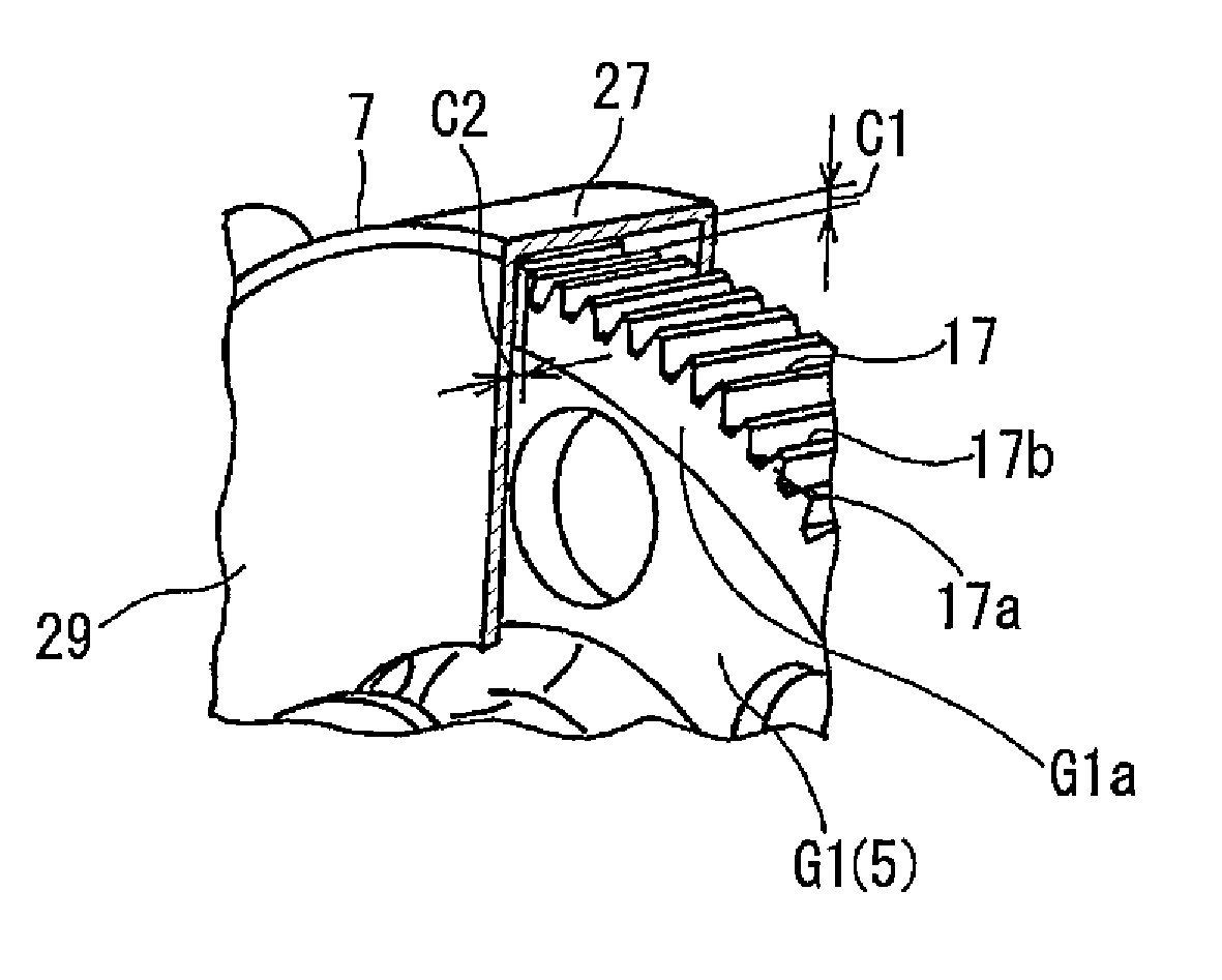
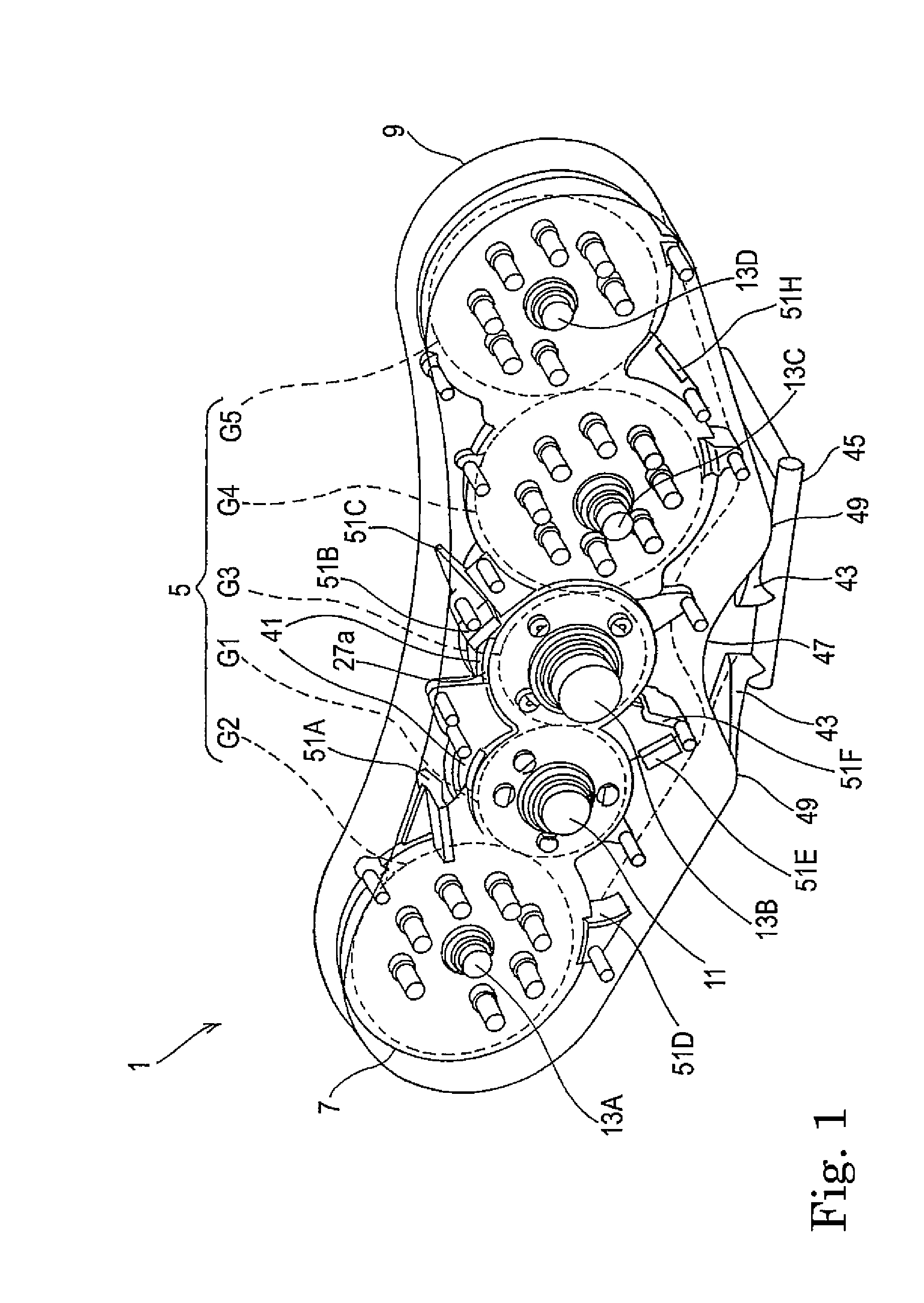
[0026]FIG. 1 is a perspective view showing a gear system 1 including a lubricating device according to preferred Embodiment 1 of the present invention. The gear system 1 includes: a gear train 5 including a plurality of (five in the present embodiment) gears G1 to G5 meshing with one another; a shroud 7 covering the gear train 5; and a housing 9 covering the shroud 7 such that space is formed between the housing 9 and the shroud 7. FIG. 1 gives a transparent view of the housing 9, showing the shroud 7 disposed within the housing 9.

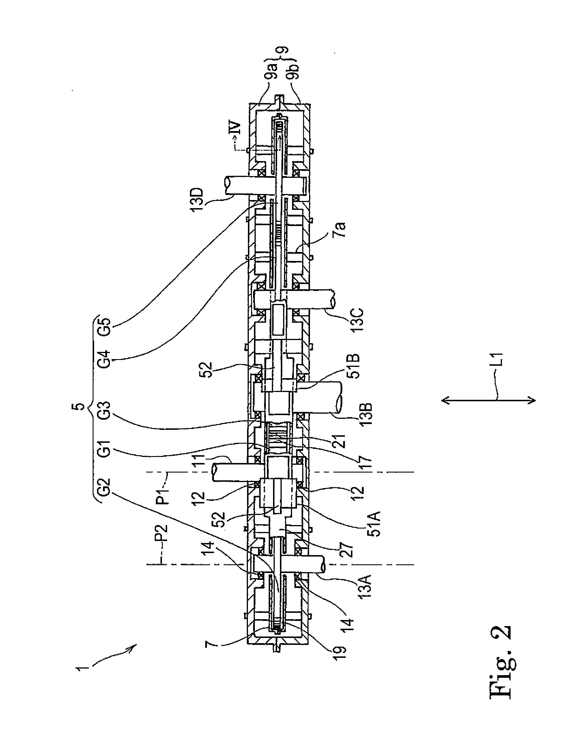
[0027]FIG. 2 is a plan view schematically showing the interior of the housing 9 of FIG. 1. As shown in FIG. 2, one of the plurality of gears G1 to G5 forming the gear train 5 is an input gear G1 which is a spur gear fixed to an input shaft 11. The input shaft 11 is rotatably supported by the housing 9 via a pair of bearings 12. One end of the input shaft 11 is connected to a power source such as a jet engine via a power transmission device which is not sho...

embodiment 2

[0047]FIG. 8 shows the gear system 1 including a lubricating device according to preferred Embodiment 2 of the present invention. FIG. 9 is a front view showing the operation of the gear system 1. In the gear system 1 according to Embodiment 2, the oil-drain ports 41 in the gear system 1 according to Embodiment 1 shown in FIG. 1 are provided only at the upper side of the shroud 7. Except this feature and other points specifically described below, the gear system 1 according to Embodiment 2 has the same structure as that described in Embodiment 1.

[0048]As shown in FIGS. 8 and 9, the shroud 7 is provided so as to cover the five gears G1 to G5 forming the gear train 5. The upper wall portion 27a of the shroud 7 is provided with a total of five oil-drain ports 41 corresponding to the respective gears G1 to G5. On the other hand, the lower wall portion 27b of the shroud 7 is provided with a plurality of oil-drain holes 53 extending through the lower wall portion 27b. In the present embod...


PUM


Abstract

A lubricating device for a gear train (5) including a plurality of gears meshing with each other includes a shroud (7) configured to cover the gear train (5) and a housing (9) configured to cover the shroud (7). The shroud (7) includes: an oil supply nozzle (25) configured to supply oil (OL) to a meshing position (21) of the gear train (5); and oil-drain ports (41) through which the oil (OL) is discharged from the shroud. The housing (9) includes, at its lower part, a draw-out port (43) through which the oil (OL) discharged from the oil-drain ports (41) is drawn to the outside of the housing. Guide members (47) are provided between the shroud (7) and the housing (9). The guide members (47) guide the oil (OL) discharged from the respective oil-drain ports (41) of the shroud (7) such that the oil (OL) flows downward through space (S) between the shroud (7) and the housing (9).

Description

TECHNICAL FIELD[0001]The present invention relates to a gear train lubricating device for use in a gear system such as a gearbox or a high-speed gear mechanism used in a gas turbine engine or a jet engine.BACKGROUND ART[0002]Such a gear system as mentioned above includes a lubricating oil supply port and a lubricating oil outlet port for use in lubricating and cooling down the gears. The lubricating oil supply port is used for spraying lubricating oil onto the gears, and the lubricating oil outlet port is used for collecting, with an oil scavenging pump, the lubricating oil that has been used for lubricating and cooling down the gears. Power loss in such a gear system is mainly caused by air resistance and lubricating oil agitation resistance, which occur when the gears rotate. Particularly in the case of an aircraft engine, the gear train rotates at a relatively high speed, and therefore, air resistance due to the rotation of the gears is great. Moreover, in aircrafts developed in ...

Claims


Application Information

Patent Timeline
IPC IPC(8): F16H57/04
CPCF16H57/0409F16H57/0421F16H57/0495F16H57/0423Y02E10/72
Inventor TANAKA, KENICHIROGOI, TATSUHIKOARISAWA, HIDENORINISHIMURA, MOTOHIKO
Owner KAWASAKI HEAVY IND LTD
Why Eureka
Try Eureka