Rapid leakage-proof structure for tubes
a leakage-proof structure and tube technology, applied in the direction of fluid pressure sealing joints, sleeves/socket joints, pipe joints, etc., can solve the problems of limited sealing effect, waste of waiting time, and time-consuming replacement, and achieve the effect of rapid leakage-proo
- Summary
- Abstract
- Description
- Claims
- Application Information
AI Technical Summary
Benefits of technology
Problems solved by technology
Method used
Image
Examples
first embodiment
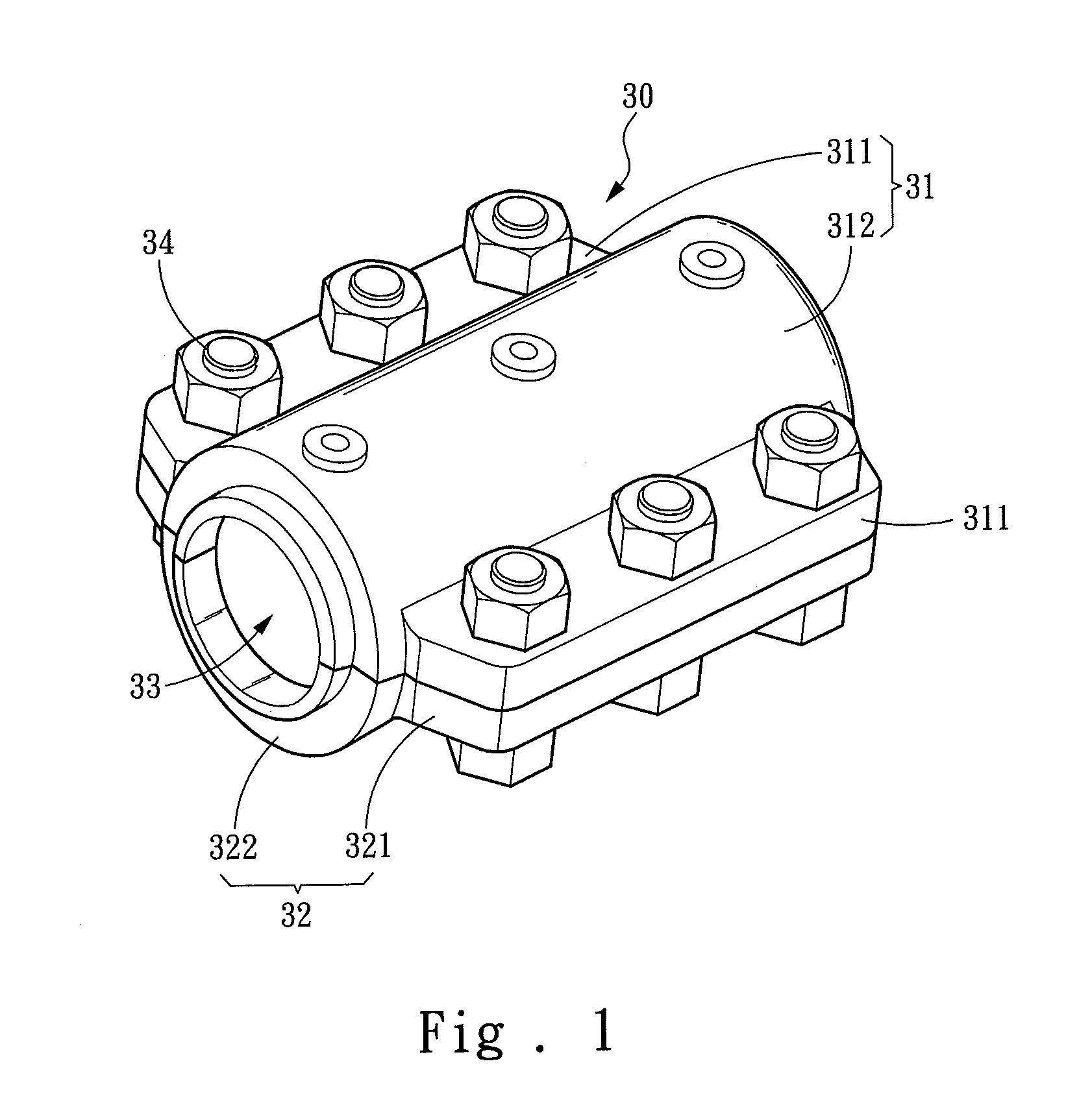
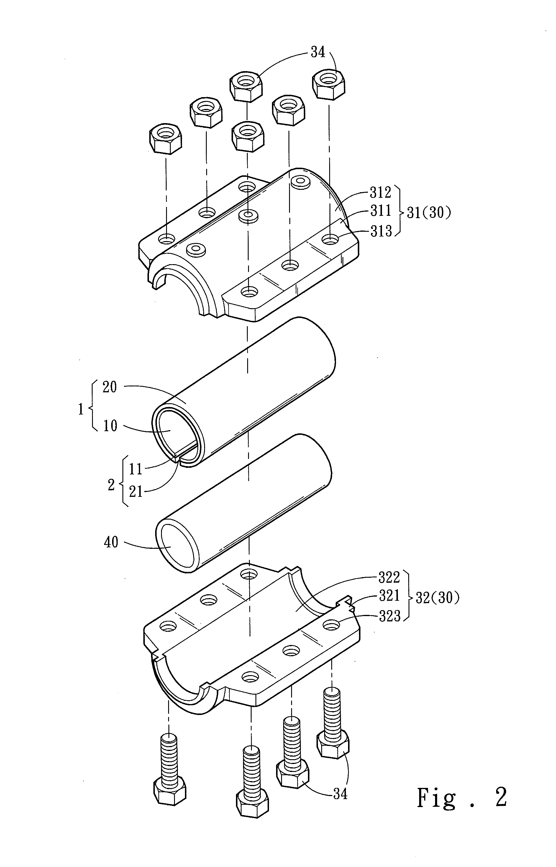
[0015]With reference to FIGS. 1-3, a rapid leakage-proof structure for tubes according to the present invention covers an outer surface of a tube 40 and comprises an inner soft layer 10 with a first hardness, an outer hard layer 20 with a second hardness, and a clamping assembly 30. The inner soft layer 10 is directly attached to the outer surface of the tube 40, and the first hardness is smaller than 60 degrees at Shore Hardness (HS). The outer hard layer 20 covers a surface at one side of the inner soft layer 10 that is far away from the tube 40, and the second hardness is greater than the first hardness. The clamping assembly 30 is disposed at one side of the outer hard layer 20 that is far away from the tube 40 to clamp the tube 40 via the outer hard layer 20 and the inner soft layer 10.
[0016]The inner soft layer 10 and the outer hard layer 20 are made of an elastic rubber material with anti-acid / base property and formed in a tubular structure. The inner soft layer 10 and the ou...
second embodiment
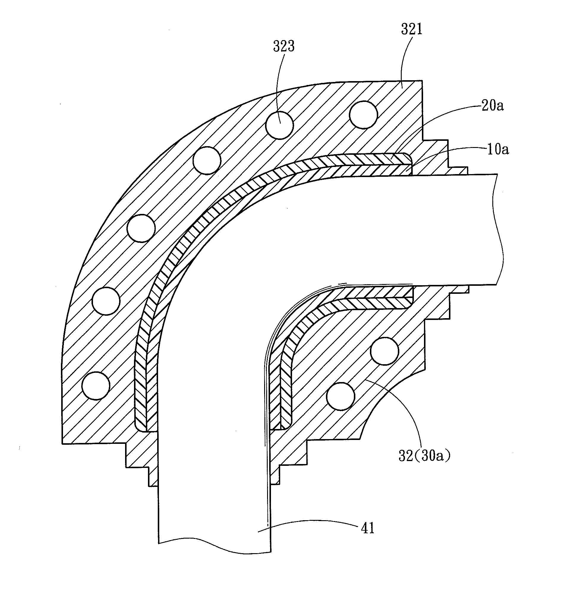
[0018]Referring further to FIG. 4, a rapid leakage-proof structure for tubes according to the present invention also can be used in a curved tube 41, wherein the rapid leakage-proof structure comprises an outer hard layer 20a and an inner soft layer 10a to incorporate with a clamping assembly 30a to cover the curved tube 41. The outer hard layer 20a and the inner soft layer 10a may have assembling slots to hold and cover the curved tube 41. Since the curved tube 41 is easy to be broken, the rapid leakage-proof structure of the present invention can stop leaking upon the leakage occurs and further prevent the leakage before the leakage occurs by covering the curved tube 41, thus a sealing effect is obtained.
third embodiment
[0019]As shown in FIG. 5, a rapid leakage-proof structure for tubes according to the present invention is applied to a T-shaped tube 42 and comprises an inner soft layer 10b, an outer hard layer 20b, and a clamping assembly 30b. Because the T-shaped tube 42 has at least one welded section, its structural strength is weaker than that of the straight tube 40 or the curved tube 40. Through the inner soft layer 10b, the outer hard layer 20b, and the clamping assembly 30b, the invention can achieve leak-proof and sealing effect.
[0020]Thereby, the rapid leakage-proof structure of the present invention is capable of covering the tube directly by means of the inner soft layer to avoid a poor sealing effect caused by corrosion of the tube or unevenness caused by welding. In addition, as the outer hard layer covers one side of the inner soft layer that is far away from the tube, thus a secure structure is obtained and the leakage problem caused by insufficient sealing pressure of the clamping...
PUM
 Abstract
Description
Claims
Application Information
 - R&D
- Intellectual Property
- Life Sciences
- Materials
- Tech Scout
- Unparalleled Data Quality
- Higher Quality Content
- 60% Fewer Hallucinations
Browse by: Latest US Patents, China's latest patents, Technical Efficacy Thesaurus, Application Domain, Technology Topic, Popular Technical Reports.
© 2025 PatSnap. All rights reserved.Legal|Privacy policy|Modern Slavery Act Transparency Statement|Sitemap|About US| Contact US: help@patsnap.com


