Individually identifiable surface acoustic wave sensors, tags and systems

a surface acoustic wave and sensor technology, applied in the field of individual identifiable surface acoustic wave sensors, tags and systems, can solve the problems of limiting the number of sensor codes that will operate simultaneously, preventing the production of larger sets within commercially useful spectral bandwidths, and all prior coded correlation-based systems suffer from difficulties. , to achieve the effect of moderate interference and good auto-correlation properties

Active Publication Date: 2013-07-18
SENSANNA
View PDF4 Cites 34 Cited by
  • Summary
  • Abstract
  • Description
  • Claims
  • Application Information

AI Technical Summary

Problems solved by technology

A problem with current passive wireless coded SAW sensors and sensor-tags is the limited number of sensor codes that will operate simultaneously due to code collision interactions.
This approach has been used to produce up to 6 resonant sensors, but production of larger sets within commercially useful spectral bandwidths is precluded by bandwidth limitations and the need for guard-banding.
All of the coded correlation-based systems in prior art suffer from difficulty related to the interference between sensor responses due to code cross correlations.
However, in the systems developed to date, the codes used have not been ideal, because sets of DSSS codes that have exactly zero cross-correlation between codes for all relative time alignments simply do not exist.
This makes interpreting the reflected device responses and calibrating the sensor system difficult, and dependent on the precise sensor group choice and sensor spatial distribution.
These limitations apply not just to prior art DSSS wireless sensor systems, but to reflective tapped delay line devices, OFC, and other systems that utilize code diversity in any form, since truly ideal, perfectly non-interacting codes cannot be realized using any of the techniques known to date.

Method used


Image

  • Individually identifiable surface acoustic wave sensors, tags and systems
  • Individually identifiable surface acoustic wave sensors, tags and systems
  • Individually identifiable surface acoustic wave sensors, tags and systems

Examples


Embodiment Construction

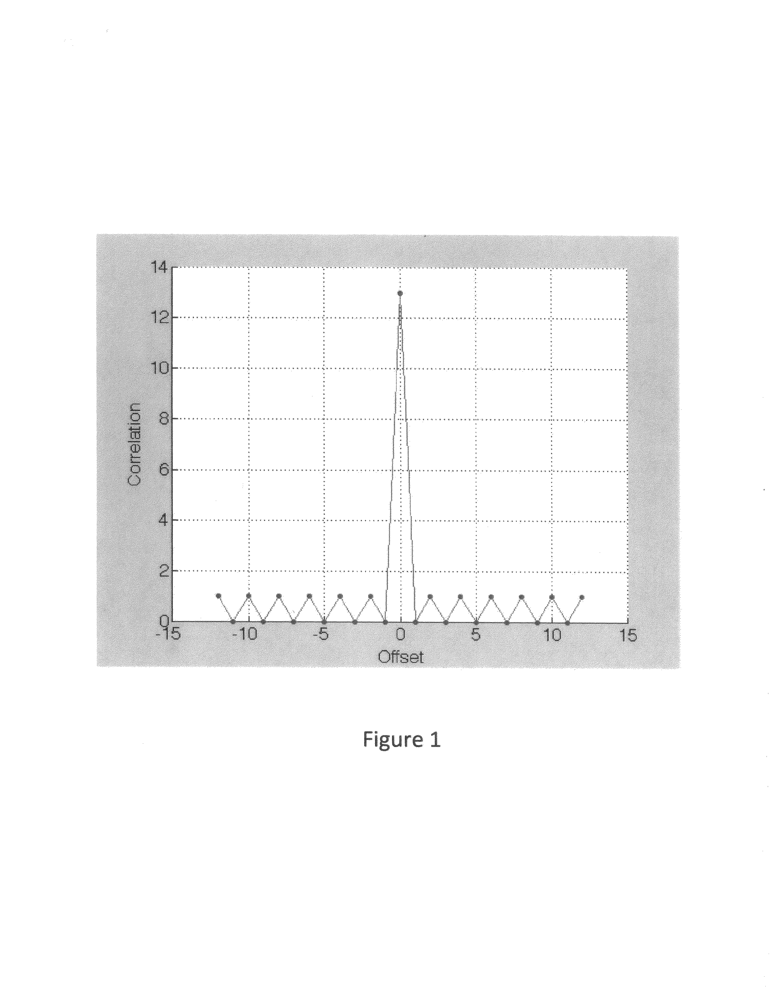
[0049]Embodiments of the present invention teach methods for developing sets of individually identifiable SAW sensor tag devices that operate well together, incorporating diversity techniques and codes that have good autocorrelation properties and low cross correlation properties over a desired time range, substantially reducing code collision interference problems.

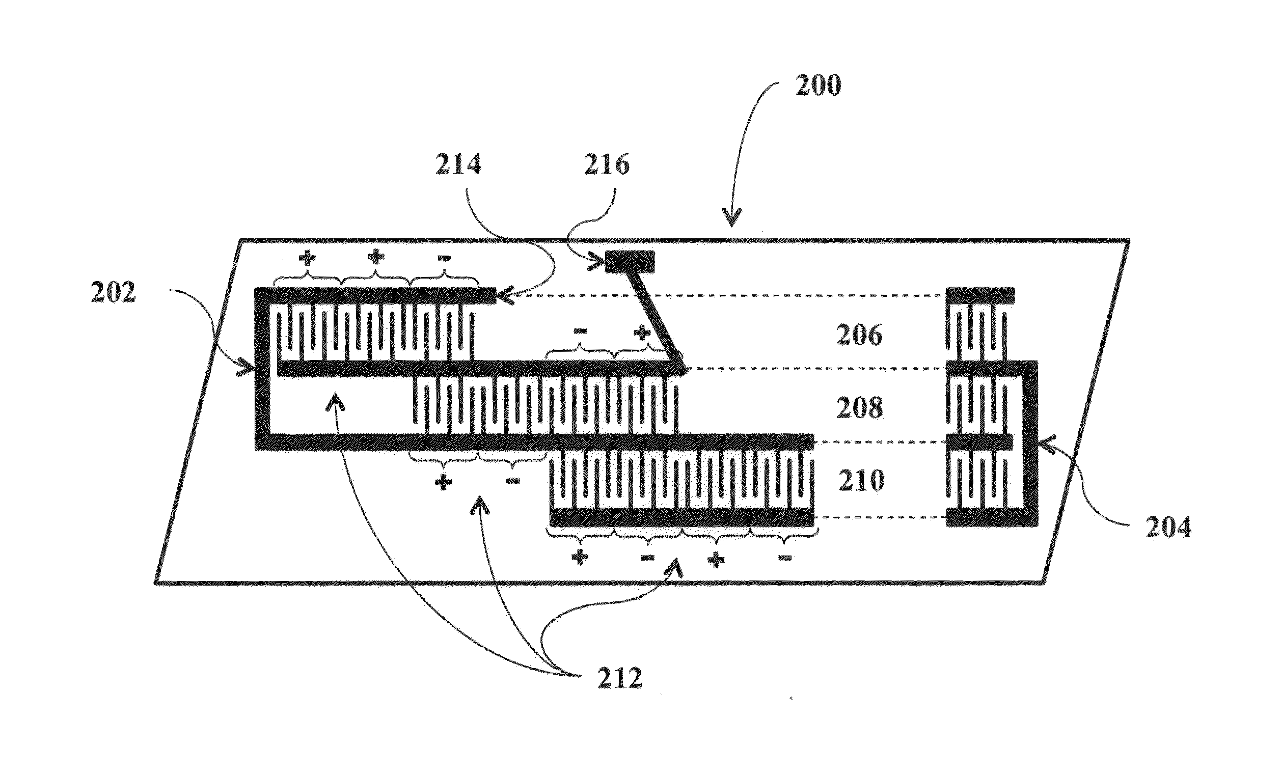
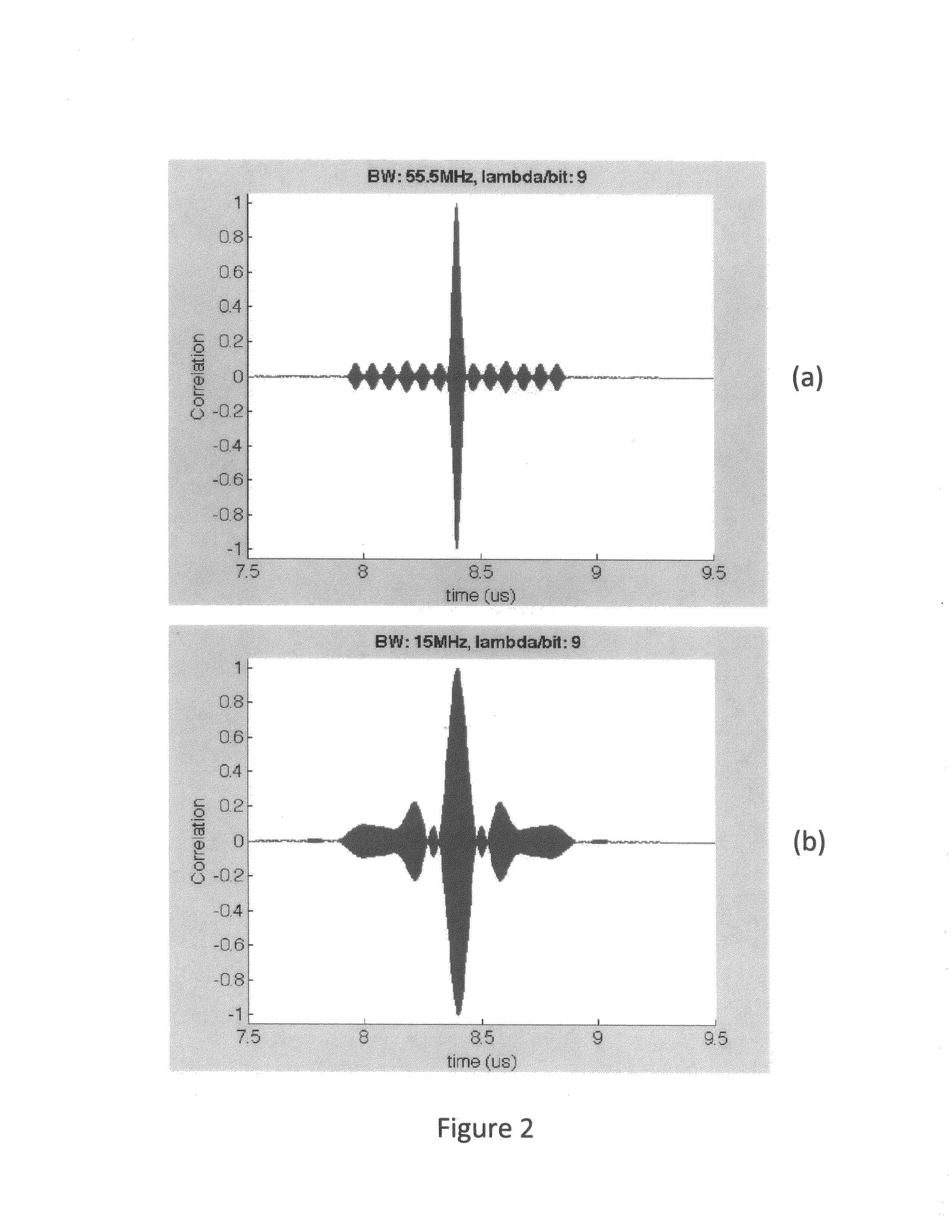
[0050]A first embodiment of the present invention utilizes direct sequence spread spectrum (DSSS) coding combined with both time diversity and frequency diversity to construct sets of individually identifiable sensors or sensor-tags. DSSS coding is alternatively called BPSK (binary phase shift keying) or binary sequence coding. In this technique, a code consists of N bits, each taking on the value of either +1 or −1. The time length of the bit determines the bandwidth (BW) of the code in the frequency domain (the shorter a bit is in time, the wider the BW and vice versa). The SAW implementation of a DSSS code utilizes at ...


PUM


Abstract

A surface-launched acoustic wave sensor tag system for remotely sensing and / or providing identification information using sets of surface acoustic wave (SAW) sensor tag devices is characterized by acoustic wave device embodiments that include coding and other diversity techniques to produce groups of sensors that interact minimally, reducing or alleviating code collision problems typical of prior art coded SAW sensors and tags, and specific device embodiments of said coded SAW sensor tags and systems. These sensor / tag devices operate in a system which consists of one or more uniquely identifiable sensor / tag devices and a wireless interrogator. The sensor device incorporates an antenna for receiving incident RF energy and re-radiating the tag identification information and the sensor measured parameter(s). Since there is no power source in or connected to the sensor, it is a passive sensor. The device is wirelessly interrogated by the interrogator.

Description

CROSS-REFERENCE TO RELATED APPLICATIONS[0001]This application claims the benefit of U.S. Provisional Application No. 61 / 586,983, filed Jan. 16, 2012, herein incorporated by reference in its entirety.STATEMENT REGARDING FEDERALLY SPONSORED RESEARCH OR DEVELOPMENT[0002]This invention was made with government support under contract NNX10CD41P awarded by the National Aeronautics and Space Administration (NASA). The government has certain rights in the invention.BACKGROUND OF THE INVENTION[0003]1. Field of the Invention[0004]Embodiments of the present invention relate to apparatus, systems, devices, and methods for remotely sensing and / or providing identification information using sets of surface acoustic wave (SAW) based sensor tag devices and systems incorporating such devices. In particular, embodiments of the present invention relate to improved methods for implementing coding and other diversity techniques within SAW sensors and tags to produce sets of individually identifiable devi...

Claims


Application Information

Patent Timeline
Patent Type & Authority Applications(United States)
IPC IPC(8): H04L25/02H01L41/08H03H9/25
CPCH04L25/02H03H9/25H01L41/08H04B2001/6912H04B1/69H04J13/107H03H9/6406H10N30/00
Inventor HINES, JACQUELINE H.SOLIE, LELAND P.TUCKER, DANA Y.G.HINES, ANDREW T.
Owner SENSANNA
Why Eureka
Try Eureka