Dry type cleaning case and dry type cleaning device

a cleaning device and a technology of a cleaning case, applied in the direction of cleaning equipment, circuit masks, manufacturing tools, etc., can solve the problems of deteriorating the performance of the jig, increasing costs, and inflicting a huge workload on workers

Inactive Publication Date: 2013-08-01
RICOH KK
View PDF0 Cites 3 Cited by
  • Summary
  • Abstract
  • Description
  • Claims
  • Application Information

AI Technical Summary

Benefits of technology

[0020]The present invention has been made in view of the above-described problems, and it is an object of at least one embodiment of the present invention to provide a dry type cleaning case capable of preventing a cleaning medium from flying out of the opening without requiring a special operation when the opening is separated from the cleaning object after the cleaning process is completed, and a dry type cleaning device including the dry type cleaning case.
[0021]An aspect of the present invention provides a dry type cleaning case for cleaning a cleaning object by causing a cleaning medium to fly by a revolving airflow and applying the cleaning medium to the cleaning object, the dry type cleaning case including a case unit; and a cleaning medium leakage prevention unit, wherein the case unit includes an inner space in which the cleaning medium flies, an opening that contacts the cleaning object so that the cleaning medium collides with the cleaning object, a ventilation path through which air flows into the inner space from outside, a suction opening that suctions the air that has been guided into the inner space through the ventilation path, to generate the revolving airflow in the inner space, and a porous unit through which a substance removed from the cleaning object is passed to the suction opening, wherein the cleaning medium leakage prevention unit prevents the cleaning medium from leaking outside through the opening from the inner space, by causing outer air to flow in when the case unit is separated from the cleaning object.

Problems solved by technology

When such a mask jig (referred to as dip pallet or carrier pallet) is repeatedly used, flux accumulates and adheres onto the surface of the mask jig, thus deteriorating the performance of the jig.
Therefore, a large amount of solvent is used, which inevitably leads to increased costs.
Furthermore, a huge workload is inflicted on the worker.
However, this method also requires a large amount of solvent.
However, in this method, because the revolving airflow is formed by the compressed air current, the cleaning medium leaks out of the container when the cleaning object is separated from the opening.
However, other problems arise by providing the net member, such as a decrease in the energy when the cleaning medium collides with the cleaning object, and a decrease in the cleaning performance as the cleaning medium gets caught in the net member.
However, when the cleaning object is separated from the opening, the opening / closing lid needs to be quickly moved to block the opening.
Thus, excessive attention and workload is required of the worker.
Furthermore, the mechanism is complex and hard to operate, and is prone to break down.
Thus, thin flakes of the cleaning medium are caused to fly.
Furthermore, a net-type porous member is provided, which allows air and dust to pass into the case but does not allow the cleaning medium to pass outside the case, so that the cleaning medium stays in the area where the revolving airflow is formed.
However, if the ventilation path needs to be blocked after the cleaning process, troublesome operations are required of the worker.
Besides, if the worker forgets to block the ventilation path, this problem cannot be solved.Patent Document 1: Japanese Laid-Open Patent Application No.

Method used


Image

  • Dry type cleaning case and dry type cleaning device
  • Dry type cleaning case and dry type cleaning device
  • Dry type cleaning case and dry type cleaning device

Examples


example

[0180]In this example, a pallet on which flux is adhering was used as a sample of a cleaning object. The pallet was made of epoxy resin including glass fiber. The pallet is used for masking areas of a PCB (print-circuit board) during a soldering procedure performed with a flow solder bath. By repeatedly using this kind of mask jig, flux accumulates on the mask jig as a thick film. Therefore, the flux needs to be removed periodically. The pencil hardness of the adhered flux was 2B. The thickness of the flux was 0.5 mm through 1 mm.

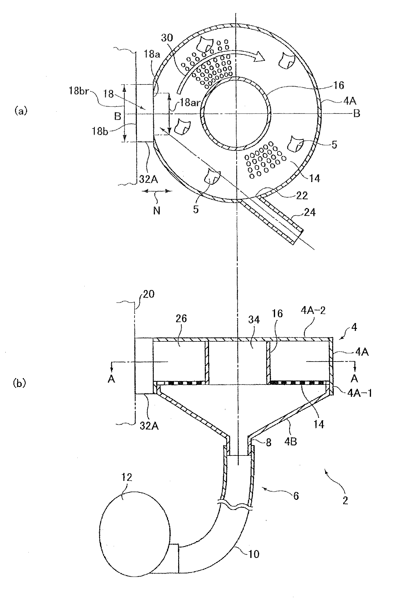
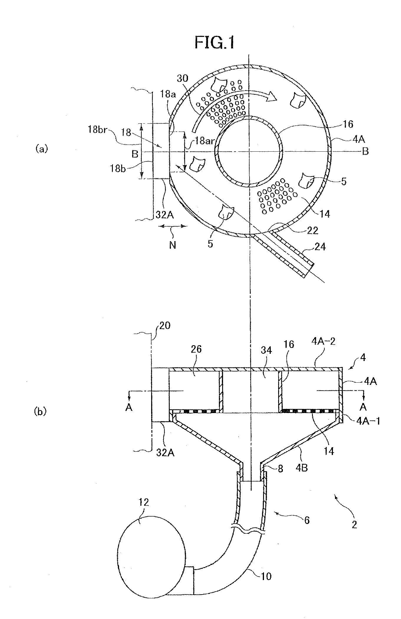
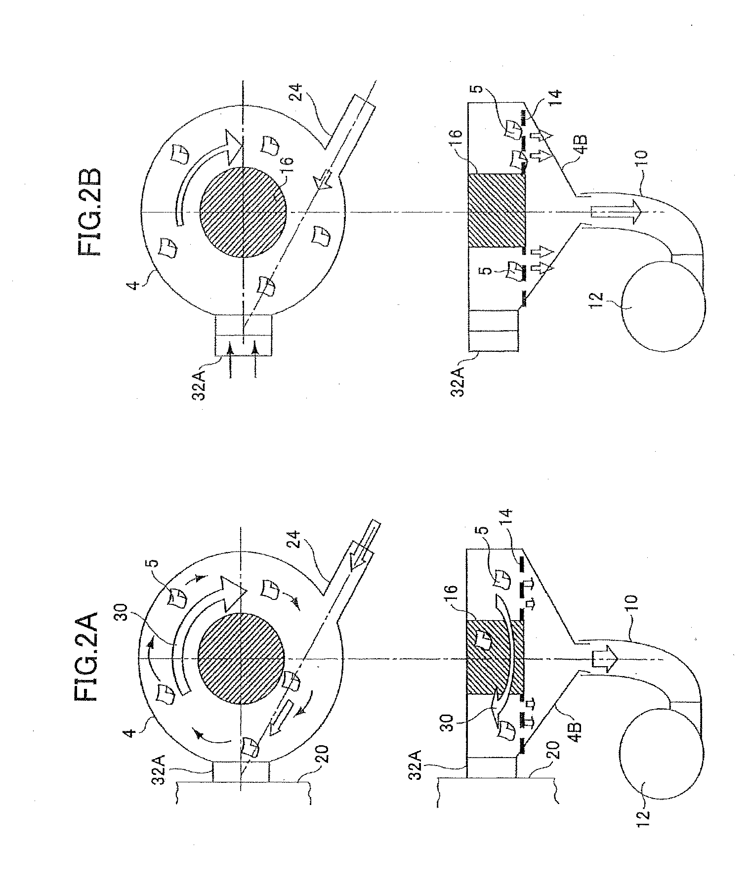
[0181]As the cleaning device, the dry type cleaning device 2 shown in FIG. 1 was used. In the cleaning device, a suction unit having a suction capability corresponding to a vacuum degree of 20 Kpa was used. A pallet to which flux is adhering was prepared. An area of the opening 45 mm×60 mm was used as one sample unit, and the cleaning was performed for three seconds. Two grams of the cleaning medium was used for the cleaning process. Table 1 indicates the f...


PUM

PropertyMeasurementUnit
areaaaaaaaaaaa
thicknessaaaaaaaaaa
areaaaaaaaaaaa

Abstract

A dry type cleaning case is for cleaning an object with a medium that flies by a revolving airflow. The dry type cleaning case includes a case unit and a leakage prevention unit. The case unit includes a space in which the medium flies, an opening that contacts the object so that the medium collides with the object, a ventilation path through which air flows into the space from outside, a suction opening that suctions the air that has been guided into the space through the ventilation path, to generate the revolving airflow in the space, and a porous unit through which a substance removed from the object is passed to the suction opening. The leakage prevention unit prevents the medium from leaking outside through the opening from the space, by causing outer air to flow in when the case unit is separated from the object.

Description

TECHNICAL FIELD[0001]The present invention relates to a dry type cleaning device for cleaning a cleaning object by causing a flying cleaning medium to contact (or collide with) the cleaning object. More particularly, the present invention relates to a dry type cleaning device appropriately used as a handy type device that can be applied to a selected part of a cleaning object to clean the selected part, and a dry type cleaning case used in the dry type cleaning device.[0002]For example, the present invention is used for removing flux adhering to a mask jig referred to as a dip pallet or a carrier pallet, which is used in a flow solder bath procedure. More particularly, the present invention is appropriate for removing flux that has adhered to a narrow area such as the side surface or along the periphery of an opening of the cleaning object.BACKGROUND ART[0003]In recent years, a jig for masking areas other than the area subjected to a soldering process, has been frequently used in a ...

Claims


Application Information

Patent Timeline
Patent Type & Authority Applications(United States)
IPC IPC(8): B08B5/04
CPCB08B7/02B24C1/04B24C1/086B08B5/04H05K3/0073H05K3/3489B24C3/067B08B5/00B08B7/00H01L21/302
Inventor FUCHIGAMI, AKIHIROOKAMOTO, YOICHITSUKAHARA, KOHJITANEDA, YUUSUKEMURATA, SHOZO
Owner RICOH KK
Why Eureka
Try Eureka