Multilayer heat exchanger and heat exchange system

Inactive Publication Date: 2013-08-01
KOBE STEEL LTD
View PDF19 Cites 11 Cited by
  • Summary
  • Abstract
  • Description
  • Claims
  • Application Information

AI Technical Summary

Benefits of technology

[0017]According to the present invention, the compact heat exchanger havi

Problems solved by technology

In a case where the above conventional heat exchanger is used for such a multi-step type compression system, there are a problem that there is a need for a large installment area for arranging the pluralities of compressors and heat exchangers and a problem that there is a larger installment area due to complicated piping when the numbers

Method used


Image

  • Multilayer heat exchanger and heat exchange system
  • Multilayer heat exchanger and heat exchange system
  • Multilayer heat exchanger and heat exchange system

Examples


first embodiment

(Outline of Heat Exchange System)

[0028]With reference to the drawings, a heat exchange system according to a first embodiment of the present invention will be described.

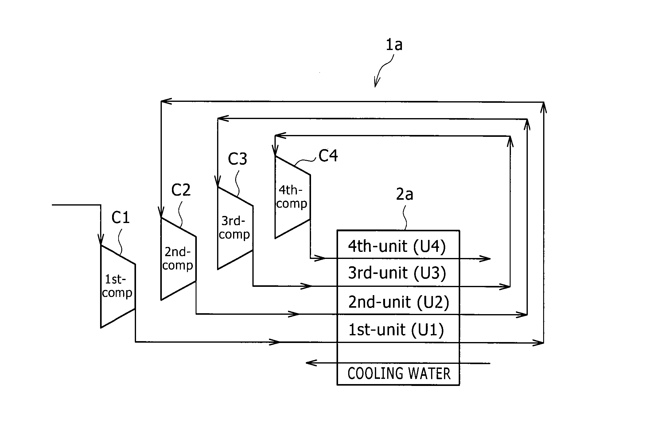
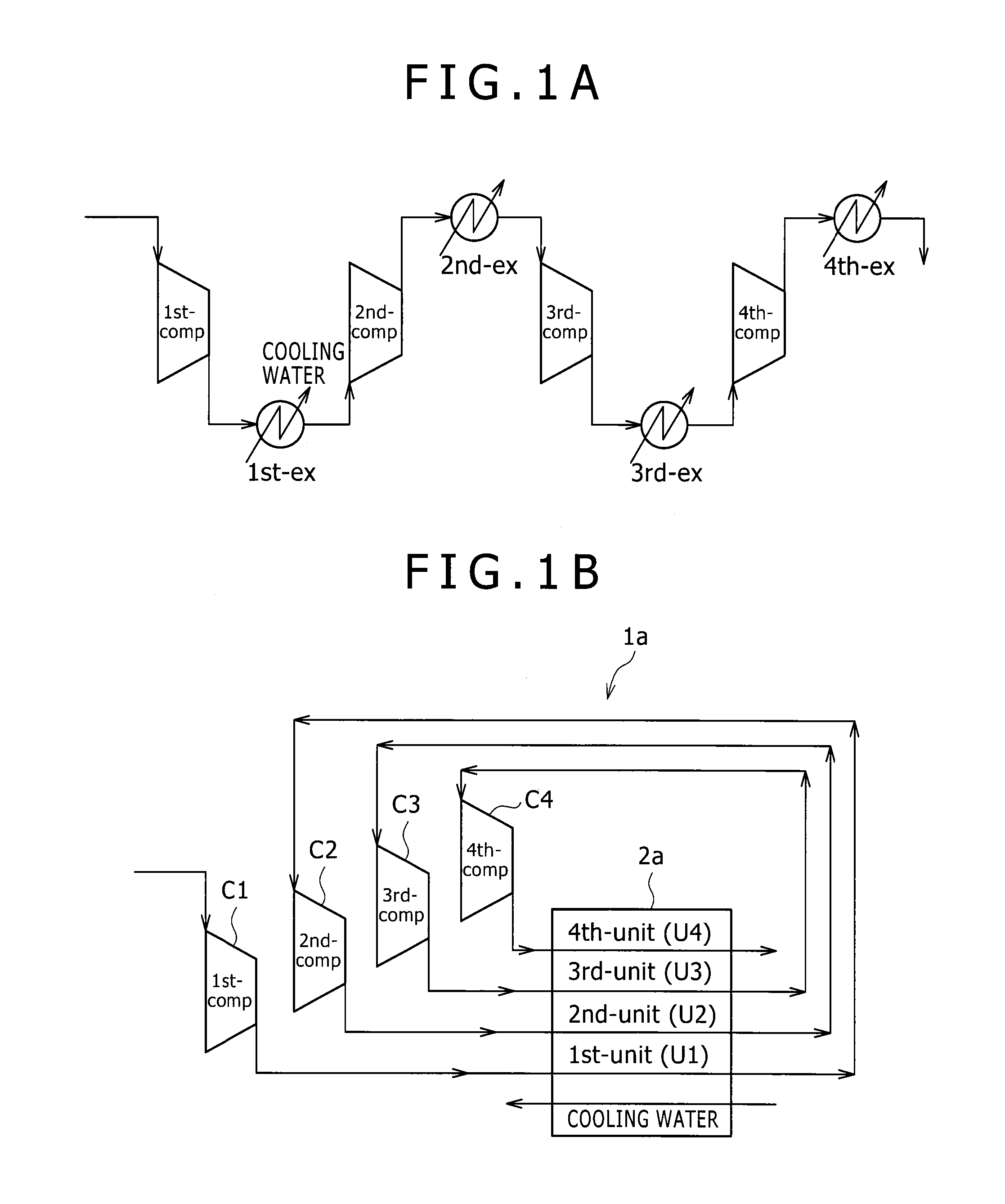
[0029]FIG. 1 is a concept view showing a configuration of a multi-step type heat exchange system in which compressors serving as a plurality of machines and a plurality of heat exchangers are used. FIG. 1A is a concept view showing a configuration of a heat exchange system in which conventional heat exchangers are used, and FIG. 1B is a concept view showing a configuration of a heat exchange system 1a in which a multilayer heat exchanger 2a according to the present embodiment is used.

[0030]In the heat exchange system 1a to be described in the present embodiment, in a multi-step type compression process for successively pressurizing and compressing a gas by a plurality of compressors connected in series so as to change the gas into a high-pressure gas, the heat exchanger is provided in a subsequent step to the compres...

second embodiment

[0105]With reference to FIGS. 7 to 9, a heat exchange system 1b according to a second embodiment of the present invention will be described.

[0106]In the heat exchange system 1b according to the present embodiment, six compressors C1 to C6 and six heat exchange units U1 to U6 are connected in series so as to perform a six-step compression. That is, a configuration of a multilayer heat exchanger 2b formed by stacking the six heat exchange units U1 to U6 is different from the configuration of the multilayer heat exchanger 2a according to the first embodiment. Thus, the configuration will be described in detail below.

[0107]The multilayer heat exchanger 2b according to the present embodiment is different from the multilayer heat exchanger 2a according to the first embodiment in terms that a configuration of a cooling plate CP2 is different from the cooling plate CP1 of the multilayer heat exchanger 2a according to the first embodiment, and the fifth heat exchange unit U5 and the sixth he...


PUM


Abstract

In a multilayer heat exchanger of the present invention, a plurality of heat exchange units for performing heat exchange of a fluid fed from a plurality of compressors is stacked. Each of the heat exchange units has a structure that pluralities of flow passage plates and cooling plates are stacked. Concave grooves formed on surfaces are formed as flow passages of the fluid in the flow passage plates and cooling plates. The flow passage plates and cooling plates are made of metal, the flow passages are formed by chemical etching, and the stacked metal flow passage plates and cooling plates are bonded to each other by diffusion-bonding. Further, each of the heat exchange units is in one-to-one correspondence with each of the compressors.

Description

BACKGROUND OF THE INVENTION[0001]1. Field of the Invention[0002]The present invention relates to a multilayer heat exchanger formed by stacking flow passage plates, and a heat exchange system in which this multilayer heat exchanger is used.[0003]2. Description of the Related Art[0004]There is a case where a high-temperature gas compressed by a compressor is guided to and cooled in a heat exchanger and the cooled high-pressure gas is charged into a tank or a cylinder. The heat exchanger used at this time includes a so-called fin type or plate type heat exchanger, and for example Japanese Unexamined Patent Application Publication No. 2000-283668 discloses such a heat exchanger. In the plate type heat exchanger having an integral structure that an interior is partitioned into a plurality of units by a partition wall, at least one of the plurality of units has a plurality of fluid inlets or outlets, and at least one side connecting to the inlets and the outlets forms a plurality of diff...

Claims


Application Information

Patent Timeline
IPC IPC(8): F28F3/08
CPCF28D9/005F28F3/08F28D9/0056F04D29/5826F28D9/0075F28D9/0093F28D9/02F28F3/00
Inventor NOISHIKI, KOJIMIWA, YASUTAKEBAN, HIROYUKI
Owner KOBE STEEL LTD
Why Eureka
Try Eureka