
Fluorescent lamp with coated phosphor particles

a technology of phosphor particles and fluorescent lamps, which is applied in the direction of discharge tubes/lamp details, discharge tubes luminescent compositions, discharge tubes/lamp details, etc., can solve the problems of reducing the overall efficiency of lamps, reducing the phosphor conversion efficiency and lumen output of lamps over their life cycles, and most of the 185 nm wavelength radiation wasted

Inactive Publication Date: 2013-08-01
GENERAL ELECTRIC CO
View PDF5 Cites 10 Cited by
  • Summary
  • Abstract
  • Description
  • Claims
  • Application Information

AI Technical Summary

Benefits of technology

The patent describes a fluorescent lamp with a phosphor-containing layer that is light transmitting. The phosphor-containing layer is made up of particles that have a coating on them. The coating can be made of magnesium aluminate spinel, magnesium oxide, or other compounds. The phosphors used in the lamp can be yttrium vanadate, strontium aluminate, strontium fluorophosphate, or barium magnesium aluminate activated with europium or manganese. The phosphor-containing layer can be made using atomic layer deposition. The patent also describes different blends of phosphors that can be used in the lamp. The technical effects of this patent include improved color rendering, reduced color center formation, and reduced energy consumption.

Problems solved by technology

But in reality, most of the 185 nm wavelength radiation is wasted, which lowers the overall efficiency of the lamp.
Moreover, 185 nm emission also leads to formation of color center—a type of point defect-in phosphors, which decreases the phosphor conversion efficiency and lumen output of lamps over their life cycle.
There are other notable problems associated with phosphors in fluorescent lamps.
These problems lead to the overall degradation of phosphors and their lumen output over life.
However, it is our understanding that they have been excluded from current commercial use in fluorescent lamp manufacturing because of their very severe lumen depreciation during lamp operation.
The discrete spectra which characterize phosphor blends will yield good color rendering of objects whose colors match the spectral peaks, but not as good of objects whose colors lie between the spectral peaks.

Method used


Image

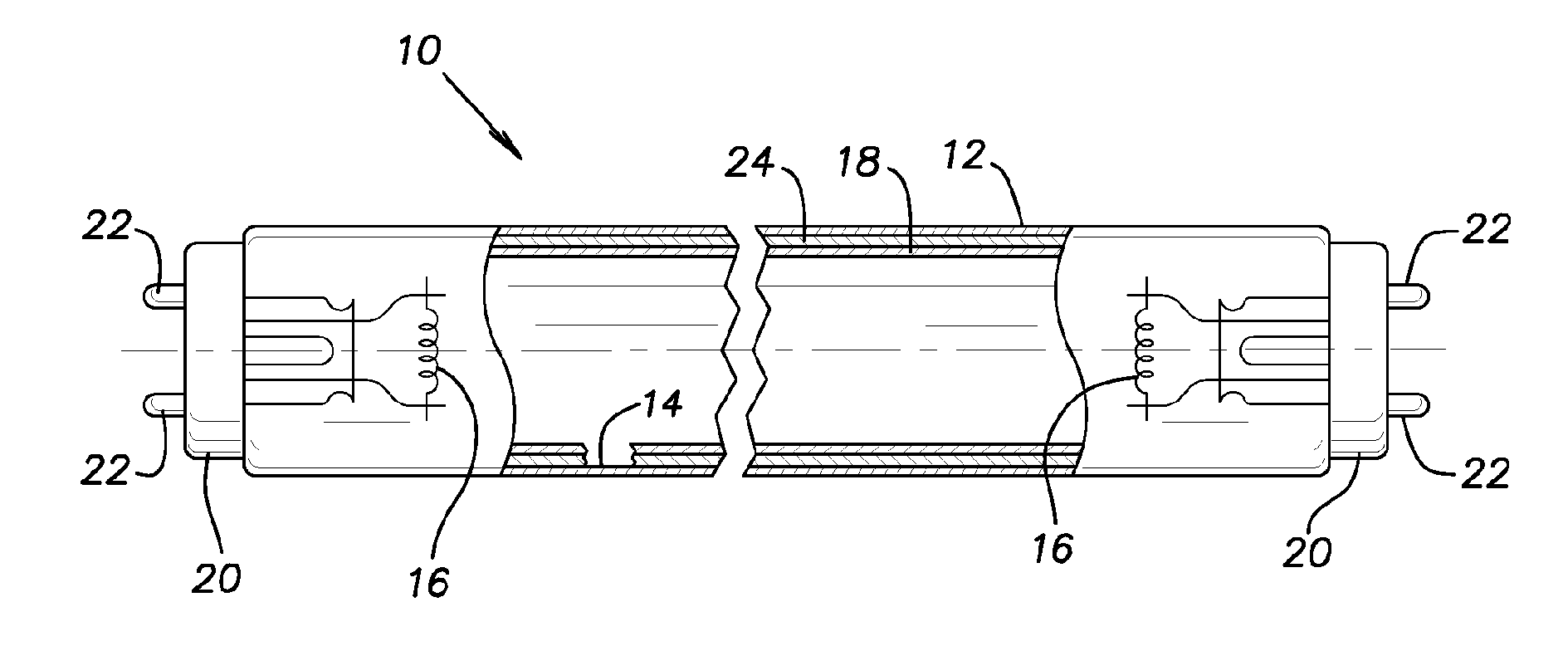
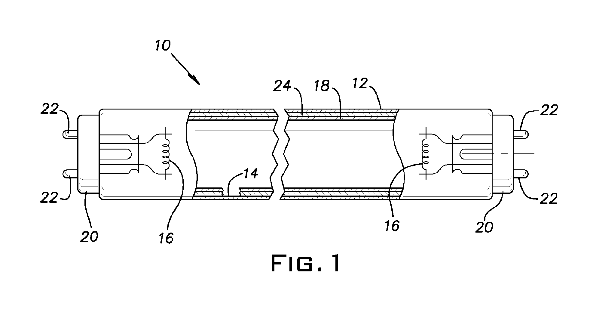
  • Fluorescent lamp with coated phosphor particles
  • Fluorescent lamp with coated phosphor particles

Examples


example

[0081]Table 2 simulates lamp performance at 100 hour burning. A spreadsheet is used to mathematically sum from a library of spectra to simulate lamp performance. The individual spectra were obtained for unblended one component phosphors for each of red, green and blue and the properties were measured for lamps coated with these phosphors at 100 hours of burning. Phosphor blends were then simulated using the spreadsheet by using proportions of each of the red, green and blue one component blends (spectral percentages) to produce a white blend and estimating the LPW and CRI for lamps using the blend based on the measured LPW and CRI for the lamps that include only one of each component. This gives reasonable estimates of the spectra and the LPW. The CRI values shown for R1-14 are calculated from the spectra with standardized formulas described above. To make phosphor compositions from the blends and their spectral percentages, one would start out with blends using the spectral % of ea...


PUM


Abstract

This disclosure features fluorescent lamps that include a phosphor layer including at least one phosphor, which in the past has not been commercially usable in lamps or in some cases suffers from performance problems such as poor brightness. These problems of the phosphors were caused, for example, by mercury ion bombardment or exposure to 185 nm radiation from the discharge. These problems are expected to be avoided by coating particles of one or more of the phosphors, such as using atomic layer deposition in which the coating is not more than 500 nm in thickness. Examples of phosphors that can be coated are yttrium vanadate activated with europium or yttrium vanadate phosphate activated with europium. The coating can be selected from the group consisting of alumina, yttria, lanthanum oxide, magnesium aluminate spinel, magnesium oxide and combinations thereof.

Description

FIELD OF THE INVENTION[0001]This disclosure pertains to a fluorescent lamp including a coated phosphor, in particular, to a lamp including at least one phosphor that has a thin coating applied using atomic layer deposition.BACKGROUND OF THE INVENTION[0002]Fluorescent lamps are well known and comprise a tubular hermetically sealed glass envelope including electrodes at ends thereof. Inside the envelope is an arc discharge sustaining medium, usually at a low pressure, including inert gases and a small amount of mercury. The inside of the glass envelope is typically coated with a layer of phosphor, which absorbs ultraviolet electromagnetic radiation of 254 nm and 185 nm generated by the excited mercury arc and emits in a region of visible light.[0003]Fluorescent lamps usually experience a gradual decrease in light output (measured in lumens) with the increase of lamp usage (measured in hours burned). Ideally, the phosphor should absorb the 254 nm and 185 nm emission strongly and conver...

Claims


Application Information

Patent Timeline
IPC IPC(8): H01J61/44
CPCC09K11/7734C09K11/7787C09K11/025C09K11/7739H01J61/44H01J61/46C09K11/7736
Inventor COHEN, WILLIAM ERWINBEERS, WILLIAMSRIVASTAVA, ALOKBALAZS, LASZLODEME, ISTVAN
Owner GENERAL ELECTRIC CO
Learn More