Ultrasonic diagnostic apparatus and ultrasonic image display method

a diagnostic apparatus and ultrasonic technology, applied in tomography, instruments, applications, etc., can solve the problems of difficult display of tumors and surrounding tissue, and achieve the effect of broadening the potential for ultrasonic diagnosis

Inactive Publication Date: 2013-08-01
HITACHI LTD
View PDF3 Cites 14 Cited by
  • Summary
  • Abstract
  • Description
  • Claims
  • Application Information

AI Technical Summary

Benefits of technology

[0027]In accordance with the present, invention, a tomographic image can foe generated in which a tomographic projection image and other ultrasonic projection images such as an elasticity projection image are combined. As a result, the potent

Problems solved by technology

However, the tissue which surrounds a tumor area is generally solid, thus the tumor is hidden from a point of sight by the high luminance in the surrounding tissue and it is difficult to

Method used


Image

  • Ultrasonic diagnostic apparatus and ultrasonic image display method
  • Ultrasonic diagnostic apparatus and ultrasonic image display method
  • Ultrasonic diagnostic apparatus and ultrasonic image display method

Examples


embodiment 1

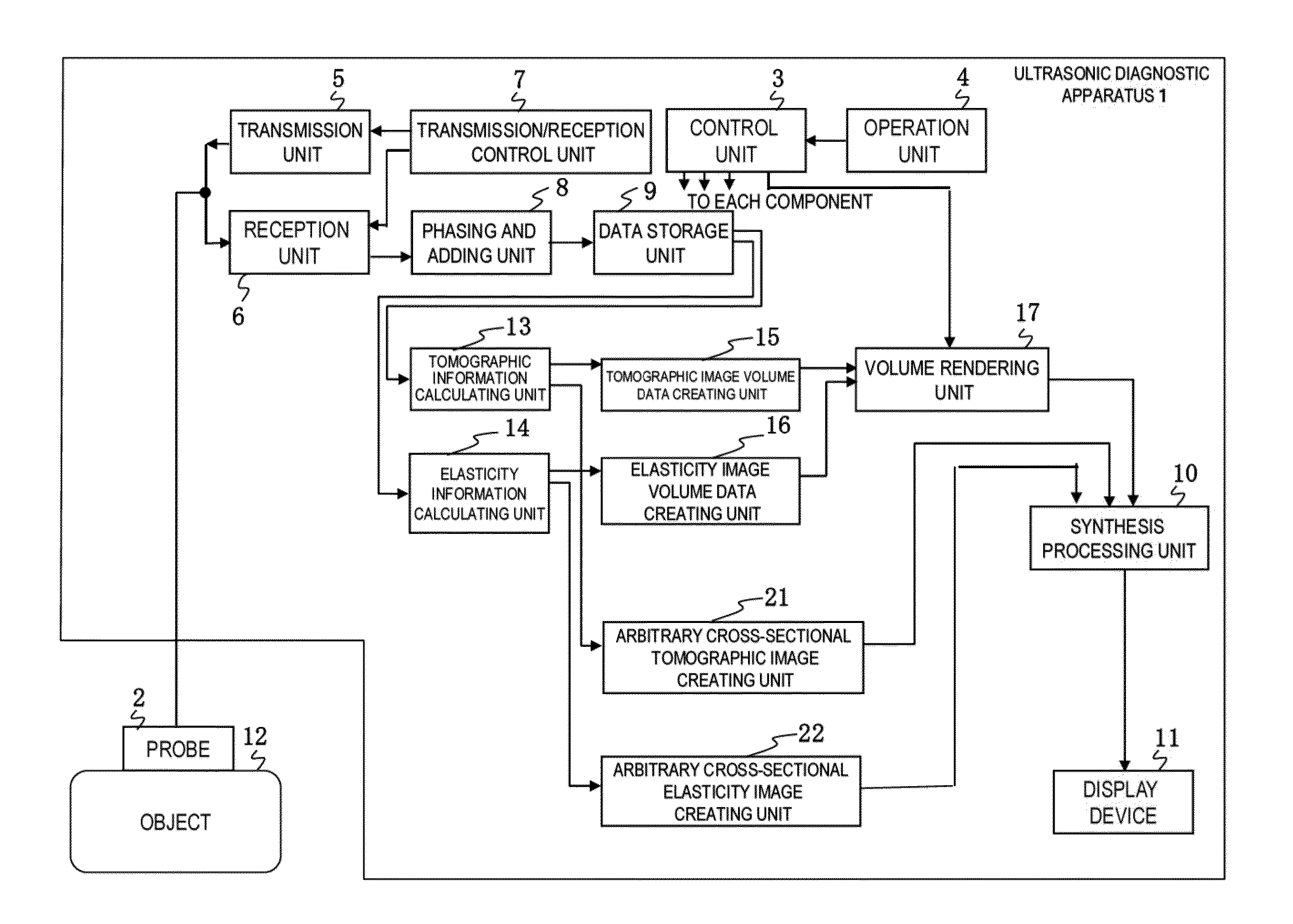
[0041]FIG. 1 shows a block configuration diagram of an ultrasonic diagnostic apparatus 1 in Embodiment 1 to which the present invention is applied. As shown in the diagram, the ultrasonic diagnostic apparatus 1 comprises an ultrasonic probe 2 to be used by applying on an object 12, a transmission unit 5 configured to repeatedly transmit ultrasonic waves to the object 12 at predetermined intervals via the ultrasonic probe 2, a reception unit 6 configured to receive the reflected echo signals reflected from the object 12, a transmission / reception control unit 7 configured to control the transmission unit 5 and the reception unit 6, and a phasing and adding unit 3 configured to perform phasing and adding of the reflected echoes received by the reception unit 6.

[0042]The ultrasonic probe is provided with plural transducers arrayed therein, and a function to transmit / receive ultrasonic waves to / from the object 12 via the transducers. The ultrasonic probe 2 is formed by plural transducers...

example 1

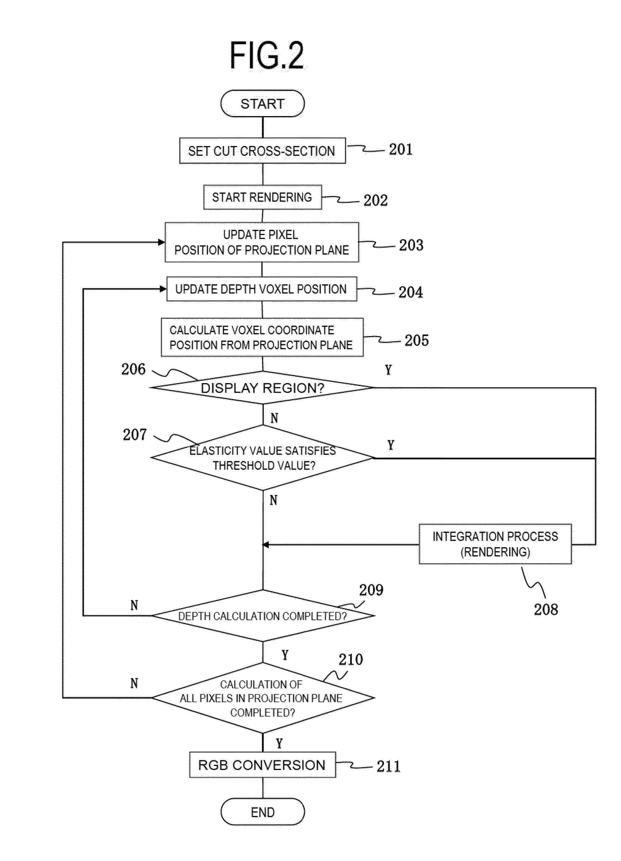
[0053]FIG. 2 is a flowchart of the volume rendering unit 17 in Example 1, and FIG. 3 is a view for explaining the characteristic of an ultrasonic projection image generated by the present example. FIG. 3(a) is a pattern diagram showing a 3-dimensional tomographic projection image 301, which is an example that a hard tumor area 302 is contained inside of soft tissue. In this case, if a normal volume rendering is performed and the surrounding tissue of the tumor area 302 is soft tissue having a higher luminance than the tumor area 302, only the soft tissue hiding the tumor area 302 is depicted as the tomographic projection image 301, thus an examiner cannot identify the tumor area 302.

[0054]Here, as shown in the pattern diagram of FIG. 3(b), for example, a cutting plane 304 is set in tomographic volume data, and the viewpoint side of the cut cross-section 304 (front side in the diagram) is set as a region in which the tomographic projection image 301 by normal volume rendering is not ...

example 2

[0068]FIG. 4 is an example of an ultrasonic projection image 400 to be displayed by the present example 2. The volume rendering unit 17 of the present example is a modification of the volume rendering unit 17 in Embodiment 1, in which a cut cross-section 404 itself which is cut by the cutting plane 304 is set in the region in which a tomographic projection image by normal rendering is not to be displayed in addition to the display in the front side of the cutting plane 304, as shown in the diagram. Then a 2-dimensional tomographic cross-sectional image 405 in the cut cross-section 404 of the tomographic projection image 401 is displayed on the cut cross-section 404. The volume rendering unit 17 generates a tomographic cross-sectional image or elasticity cross-sectional image on the cutting plane 304 on the basis of the tomographic image volume data or elasticity image volume data, and makes the generated image displayed on the display device 11. A blood vessel image 403 is depicted ...


PUM


Abstract

For generating ultrasonic projection images in which various kind of ultrasonic projection images have been appropriately combined, the invention is provided with: a storage unit that stores tomographic image volume data and elastic image volume data; a volume rendering unit that generates tomographic projection images by volume rendering on the basis of the tomographic image volume data; a display device that displays the ultrasonic projection images generated by the volume rendering unit; and an operation unit for inputting commands to control the volume rendering unit. For one of the rendering spaces partitioned by a cutting plane set in the rendering space by a command input from the operation unit, the volume rendering unit renders voxels of tomographic image volume data corresponding to the voxels of elastic image volume data that have elasticity values satisfying a set threshold value, and generates and displays the tomographic projection image on the display device.

Description

FIELD OF THE INVENTION[0001]The present invention relates to an ultrasonic diagnostic apparatus, in particular to an ultrasonic diagnostic apparatus and an ultrasonic image display method capable of constructing and displaying a tomographic projection image on which another ultrasonic projection image such as an elasticity projection image is superimposed, utilizing a property of the ultrasonic projection image.DESCRIPTION OF RELATED ART[0002]An ultrasonic diagnostic apparatus transmits ultrasonic waves to an object to be examined from an ultrasonic probe, receives the reflected echoes of the ultrasonic waves returned from the biological tissue in the object by the ultrasonic probe, and generates RF frame data by performing a reception process such as phasing on the received reflected signals. On the basis of the generated RF frame data, a grayscale 2-dimensional tomographic image is generated and displayed on a display device. Another known configuration of an ultrasonic diagnostic...

Claims


Application Information

Patent Timeline
IPC IPC(8): G06T15/08
CPCA61B8/485G06T15/08A61B8/06A61B8/14A61B8/483A61B8/466A61B8/488A61B8/5246A61B8/463
Inventor TSUJITA, TAKEHIRO
Owner HITACHI LTD
Why Eureka
Try Eureka