Image forming apparaus

a technology of forming apparatus and forming roller, which is applied in the direction of electrographic process apparatus, instruments, optics, etc., can solve the problem that the toner cannot be uniformly removed by the brush roller, and achieve the effect of efficient removal

Inactive Publication Date: 2013-08-01
KONICA MINOLTA BUSINESS TECH INC
View PDF6 Cites 11 Cited by
  • Summary
  • Abstract
  • Description
  • Claims
  • Application Information

AI Technical Summary

Benefits of technology

[0012]Thus, the seams of the first and the second brush rollers can be prevented from being in contact with the same portion on the image formation surface of the image carrier. Accordingly, even when one of the first and the second brush rollers cannot ensure a sufficient removing performance in a certain portion of the image formation surface of the image carrier due to the seam, the sufficient removing performance can be ensured by the portion of the other one of the rollers other than the seam. Thus, even when the first and the second brush rollers are used for a long period of time, the attached substances (filming) such as toner can be uniformly removed from the image formation surface of the image carrier, and thus the production of the image noise can be prevented.
[0014]Thus, the toner in the brush is uniformly distributed along the axial directions of the first and the second brush rollers. As long as the appropriate amount of the toner is accumulated in the brushes, the brushes can perform uniform removing operations over the entire first and second brush rollers in the axial directions. Thus, excellent cleaning performance can be maintained.
[0016]Thus, the brush fibers can be prevented from being excessively less densely arranged in the seam between the adjacent sections of the brush than in the other portions, and the adherence of the brush to the rotational shaft can be improved. Thus, the cleaning failure attributable to the seam can be prevented.
[0018]Thus, the scraping performances of the first and the second brush rollers can be improved. Accordingly, the cleaning performance can be further improved.
[0022]Thus, the first and the second brush rollers can efficiently remove the toner on the image carrier.
[0024]Thus, the toner (normally charged toner and oppositely charged toner) can be efficiently removed from the image carrier.

Problems solved by technology

There is a following problem in using the brush roller having such a configuration for a long period of time.
As a result, the toner cannot be uniformly removed by the brush roller.

Method used


Image

  • Image forming apparaus
  • Image forming apparaus
  • Image forming apparaus

Examples


first embodiment

1. First Embodiment

1.1. Configuration of Image Forming Apparatus

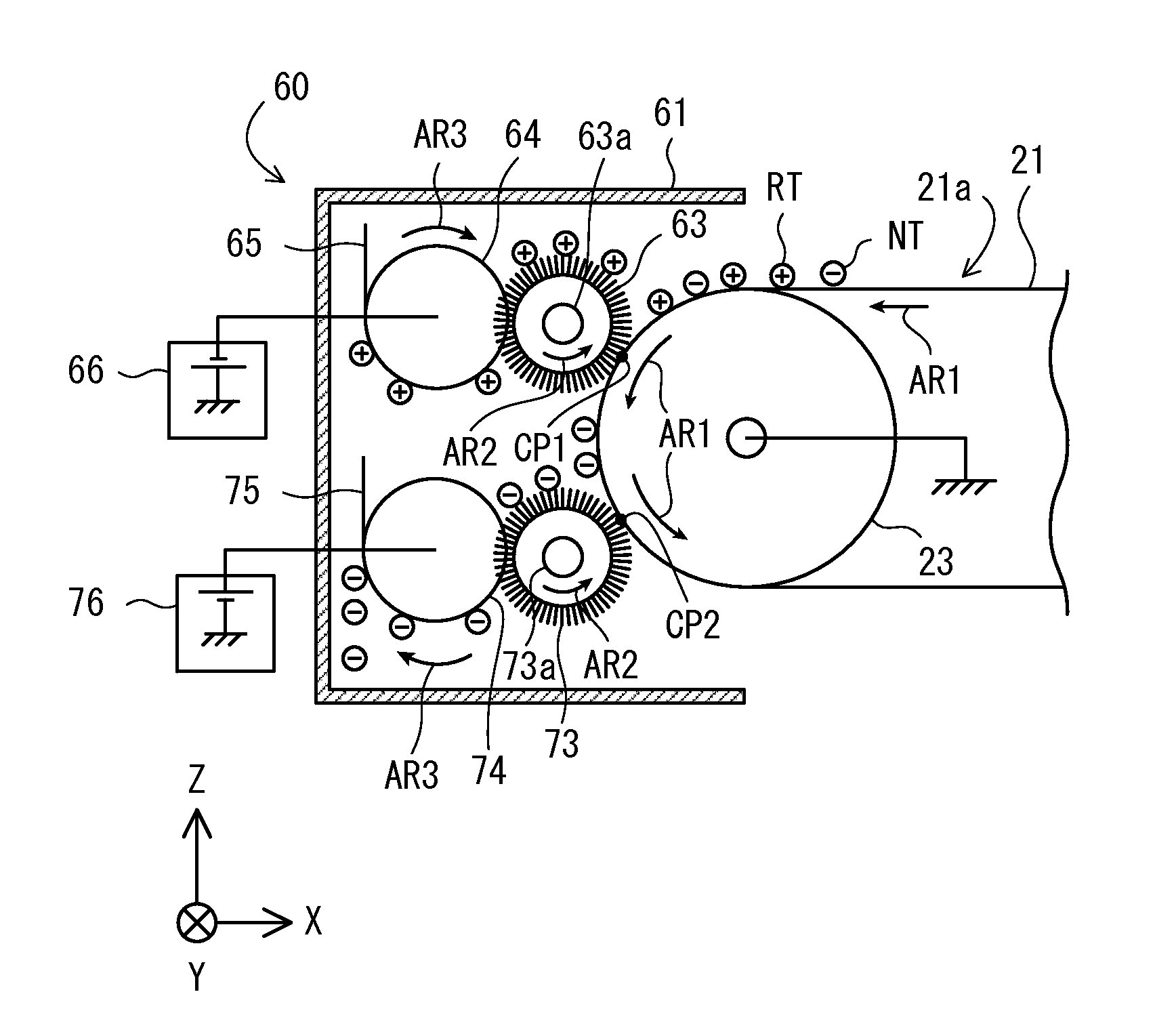
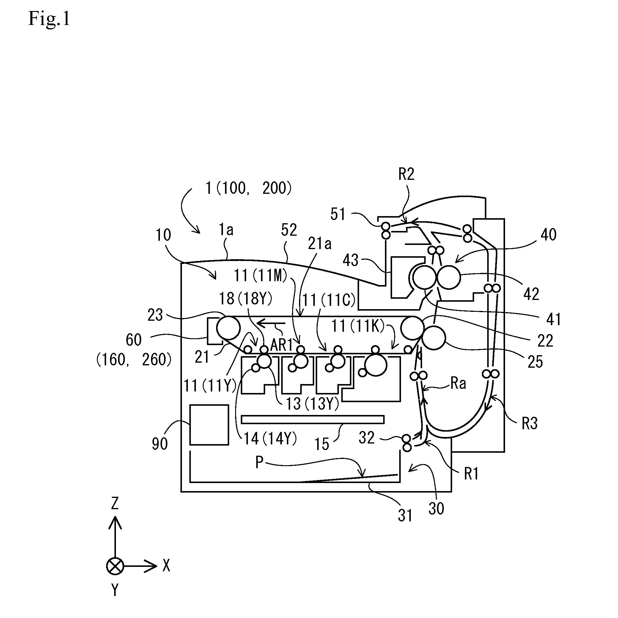
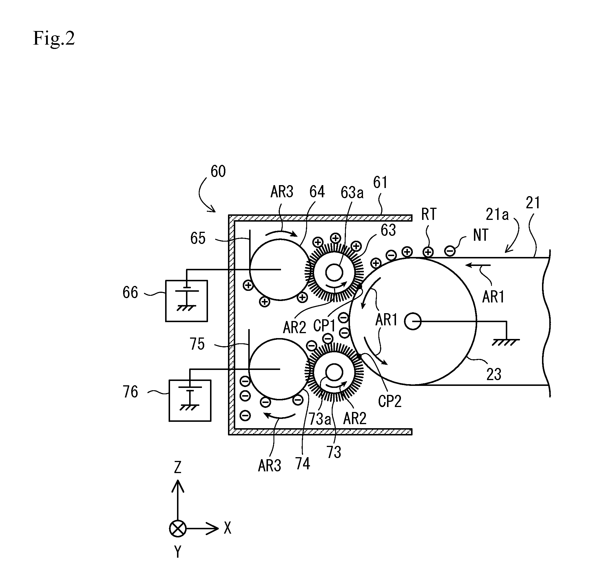
[0038]FIG. 1 is a front view showing an example of an overall configuration of an image forming apparatus 1 of an embodiment of the present invention. The image forming apparatus 1 is used as, for example, a multi-function machine integrally incorporating copy, printing, and fax capabilities, and prints a monochrome image or a color image by electrophotography. As shown in FIG. 1, the image forming apparatus 1 mainly includes a printer unit 10, a sheet feeder 30, a fixing unit 40, a discharge unit 50, and a cleaning unit 60.

[0039]FIG. 1 and subsequent drawings are provided, as appropriate, with an XYZ orthogonal coordinate system in which a Z axis direction is a vertical direction and an XY plane is a horizontal plane, to clarify the directional relationship in the drawings. Arrows provided to a sheet feed path R1, a discharge path R2, a circulation path R3, and a conveyance path Ra in FIG. 1 show “conveyance direction ...

second embodiment

2. Second Embodiment

[0095]A second embodiment of the present invention will be described below. An image forming apparatus 100 of the second embodiment has the same hardware configuration as the image forming apparatus 1 of the first embodiment, except that a plurality of lubricant suppliers 168 and 178 are provided. Thus, the difference is mainly described below.

[0096]Components common in the image forming apparatuses 1 and 100 are denoted with the same reference numerals. The components given the same reference numerals are described in the first embodiment and thus will not be described in this embodiment.

2.1. Configuration of Cleaning Unit

[0097]FIG. 7 is a front view of showing an example of a configuration of a cleaning unit 160 of the second embodiment. Like the cleaning unit 60 of the first embodiment, the cleaning unit 160 removes the remaining toner on the intermediate transfer belt 21 after the toner image is transferred onto the recording medium P from the intermediate tr...

third embodiment

3. Third Embodiment

[0108]Next, a third embodiment of the present invention will be described below. An image forming apparatus 200 of the third embodiment has the same hardware configuration as the image forming apparatus 100 of the second embodiment, except that a removing blade 279 is provided. Thus, the difference is mainly described below.

[0109]Components common in the image forming apparatuses 100 and 200 are denoted with the same reference numerals. The components given the same reference numerals are described in the second embodiment and thus will not be described in this embodiment.

[0110]FIG. 8 is a front view of showing an example of a configuration of a cleaning unit 260 of the third embodiment. Like the cleaning unit 160 of the second embodiment, the cleaning unit 260 removes the remaining toner on the intermediate transfer belt 21 after the toner image is transferred onto the recording medium P from the intermediate transfer belt 21. As shown in FIG. 8, the cleaning uni...


PUM


Abstract

Brush rollers rotate in a direction indicated by an arrow while being in contact with an image formation surface to remove toner remaining on the image formation surface from an intermediate transfer belt. The brush rollers each mainly include a rotational shaft and a brush. The brush rollers face the intermediate transfer belt with brush winding directions being opposite from one another. The brush rollers rotate in the direction indicated by the arrow. Thus, seams of the brush rollers can be prevented from being in contact with the same portion on the image formation surface of the intermediate transfer belt.

Description

CROSS-REFERENCE TO RELATED APPLICATIONS[0001]The present application claims priority under 35 U.S.C. §119 to Japanese Patent Application No. 2012-018408, filed Jan. 31, 2012. The contents of this application are incorporated herein by reference in their entirety.BACKGROUND OF THE INVENTION[0002]1. Field of the Invention[0003]The present invention relates to an image forming apparatus including copiers, printers, fax machines, and multi-function machines integrally incorporating copy, printing and fax capabilities.[0004]2. Discussion of the Background[0005]Conventionally, a technique of removing toner with preceding and trailing brush rollers arranged in parallel to the surface of a photoconductor drum has been known (for example, Japanese Unexamined Patent Application Publication No. 2005-275086).[0006]One example of a configuration of a brush roller is described.[0007]The brush roller mainly includes a rotational shaft and a brush wound around the peripheral surface of the rotation...

Claims


Application Information

Patent Timeline
Patent Type & Authority Applications(United States)
IPC IPC(8): G03G15/16G03G21/00
CPCG03G21/0011G03G21/0035G03G15/161G03G21/0076G03G21/0047
Inventor NOGUCHI, HIDETOSHIHARA, KAZUYOSHIKURODA, TAKAHIROSHIBUYA, SATORU
Owner KONICA MINOLTA BUSINESS TECH INC
Why Eureka
Try Eureka