Double-action sucker-rod well pump

a sucker-rod, double-action technology, applied in the direction of machines/engines, liquid fuel engines, positive displacement liquid engines, etc., can solve the problems of low reliability of round-trip, low efficiency of known pumps, and clogged or damaged automatic couplers, etc., to achieve high efficiency, reliable and easy-to-operate, and enhanced performance capabilities

Inactive Publication Date: 2013-08-01
KUNEEVSKIY VLADIMIR VASILEVICH
View PDF8 Cites 6 Cited by
  • Summary
  • Abstract
  • Description
  • Claims
  • Application Information

AI Technical Summary

Benefits of technology

[0006]The objective of this invention is to provide a reliable and easy-to-operate pump having high efficiency and enhanced performance capabilities.
[0007]The technical effect achieved by the invention is reduced hydraulic resistance of the upper traveling valve, the possibilities of lifting a liquid from the above-plunger and under-plunger cavities of the barrel, and setting the pump capacity by adjusting a volume ratio of its under-plunger cavity and the above-plunger cavity during a downward motion and an upward motion.
[0009]Also, the said objective is fulfilled, and the technical effect is achieved owing to the fact that a hollow rod above the upper traveling valve may be in communication with a pipe string.

Problems solved by technology

Shortcomings of this known pump are complexity and low reliability of round-trips due to the necessity of simultaneously lowering a pipe string with a pump and a plunger provided with a piston rod, with subsequent lowering of rods provided with an automatic coupler for the purpose of connecting same to the plunger.
Moreover, an automatic coupler may be clogged or damaged when being joined with the piston rod, which requires an additional round trip for cleaning or replacing the automatic coupler.
Furthermore, this known pump is characterized by a low efficiency due to high resistance in the upper traveling valve, since the latter has a very small flow section because it is arranged between the barrel and the wellbore wall.
Also, it is impossible to set this pump capacity by adjusting a volume ratio of its under-plunger cavity and the above-plunger cavity during a downward motion and an upward motion.
Shortcomings of this pump are complexity and high cost of round-trips due to the necessity of simultaneously lowering a pipe string with a pump and rods with a plunger arranged in the barrel, which requires use of lowering cranes having a stroke at least twice as great as a length of pipes in a string to be lowered.
Furthermore, this pump is characterized by low efficiency due to high resistance in the upper traveling valve, since the latter has a very small flow section because a distribution coupling is to be arranged above it, between hollow rods arranged along the barrel axis, and the pipe string wall.
Also, this pump cannot be used when liquids are mixed and for setting the pump capacity by adjusting a volume ratio of its under-plunger cavity and the above-plunger cavity during a downward motion and an upward motion.

Method used


Image

  • Double-action sucker-rod well pump
  • Double-action sucker-rod well pump

Examples


Embodiment Construction

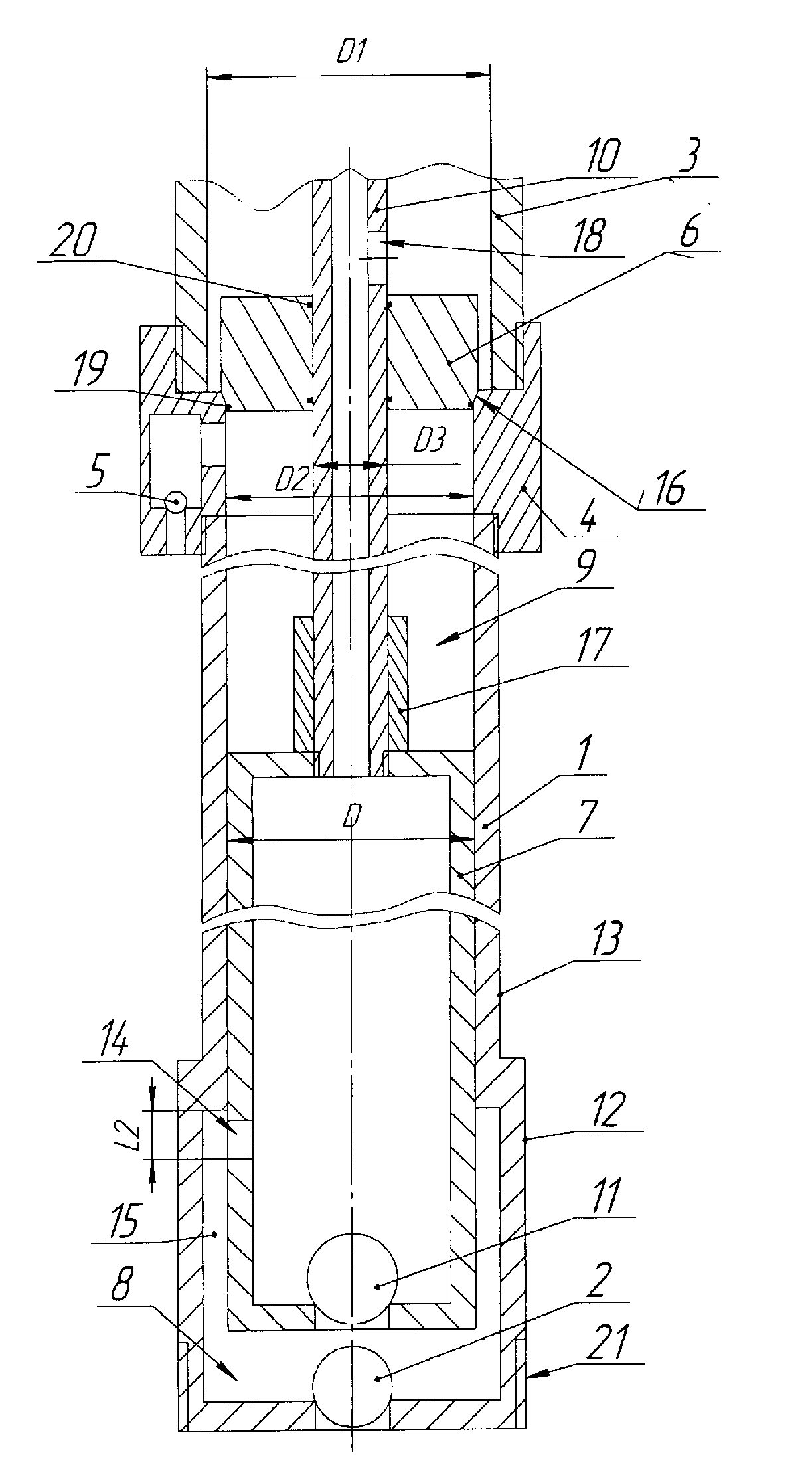
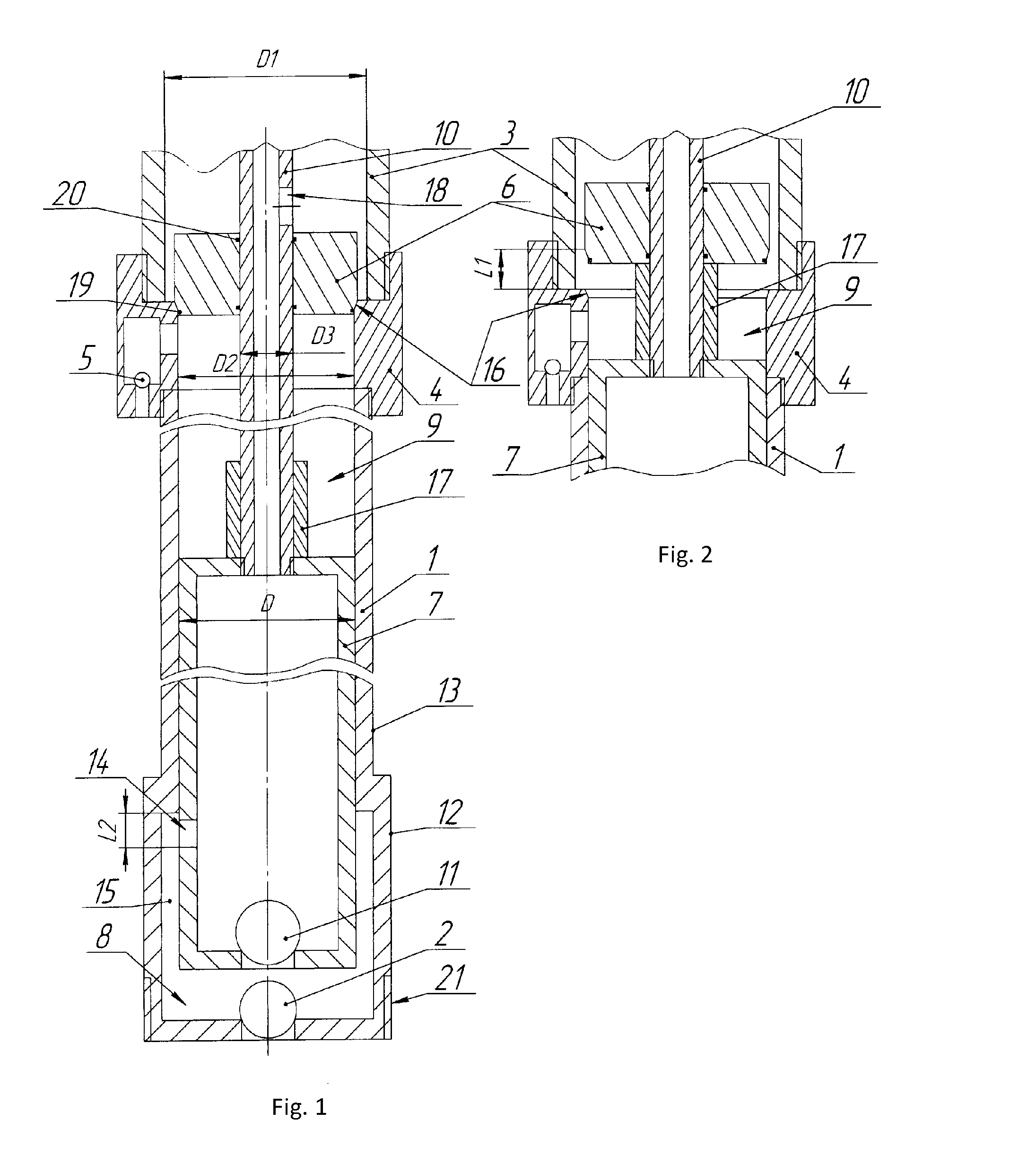
[0012]The proposed double-action sucker-rod well pump comprises a barrel 1 (FIG. 1) having a lower standing valve 2 and connected to a pipe string 3 with the use of a sub 4 provided with an upper standing valve and an upper traveling valve 5, 6 and a hollow plunger 7 arranged in the barrel 1 so as to form an under-plunger and an above-plunger cavities 8, 9, being able to move reciprocally, coupled to a hollow rod 10 and having a lower traveling valve 11. The barrel 1 is made stepped, with a lower step 12 of a greater diameter and an upper step 13 of a lesser diameter. A through hole 14 is made in the lateral wall of the plunger 7 above the lower traveling valve 11 for the purpose of communication between the cavity of the plunger 7 with a chamber 15 formed when the plunger 7 moves downwards in the lower step 12 of the barrel 1. The upper step 13 of the barrel 1 is made with an inner diameter D that is lesser than an inner diameter D1 of the pipe string 3. The sub 4 is made with an i...


PUM


Abstract

A pump includes a two-stepped cylinder with cavities and a lower intake valve, and is connected to a tubing-string via a sub, which includes an upper intake valve and discharge valve. A hollow plunger is arranged in the cylinder below and above the cavities. The plunger is connected to a hollow rod and has a lower discharge valve and a through-hole provided above the lower discharge valve to provide communication between the plunger cavity and a chamber formed as said plunger is moved downwards in a lower step of the cylinder. An upper step of the cylinder includes an inner diameter which is smaller than the inner diameter of the tubing-string. The upper discharge valve is a bush arranged on the rod with longitudinal movement upwards along said rod with excess pressure in the cylinder cavity above the plunger, and downward movement in the liquid under its own weight.

Description

FIELD OF THE INVENTION[0001]This invention relates to oil producing industry, in particular to double-action sucker-rod well pumps.PRIOR ART[0002]A double-action sucker-rod pump is known that comprises a plunger with a piston rod and an internal passage, and a barrel with a traveling valve, a standing valve and an auxiliary standing valve. A rod string is made hollow, and the barrel is provided with a passage, an auxiliary traveling valve and a sealing assembly for the plunger piston rod, which assembly is arranged on the barrel top. The under-plunger cavity of the barrel is made with the possibility of communicating with the rod string cavity via the traveling valve and the plunger inner cavity. The barrel above-plunger cavity is made with the possibility of continuously communicating with the above-packer well space via an auxiliary standing valve and with the rod string cavity via an auxiliary standing valve and a passage. Further, the rod string may be connected to the plunger p...

Claims


Application Information

Patent Timeline
Patent Type & Authority Applications(United States)
IPC IPC(8): F04B49/22
CPCF04B47/00F04B49/22E21B43/127
Inventor STRAHOV, DMITRIY VITALEVICHOSNOS, VLADIMIR BORISOVICHBESSONOV, IGOR MIKHAILOVICH
Owner KUNEEVSKIY VLADIMIR VASILEVICH
Why Eureka
Try Eureka