

Battery having cell tab connection structure using resistance welding
- Summary
- Abstract
- Description
- Claims
- Application Information
AI Technical Summary
Benefits of technology
Problems solved by technology
Method used
Image

Examples
first embodiment
[0027]Based on this basic structure of the battery, the present invention provides the following structure for connecting the tabs 111 of the cells 110 to each other. FIG. 6 is a sectional view of the battery having a cell tab connection structure according to the present invention. FIGS. 7 and 8 are, respectively, a perspective view and a plan view illustrating the battery. the cell tab connection structure in the battery according to the present invention will be described in detail with reference to FIGS. 6 through 8.
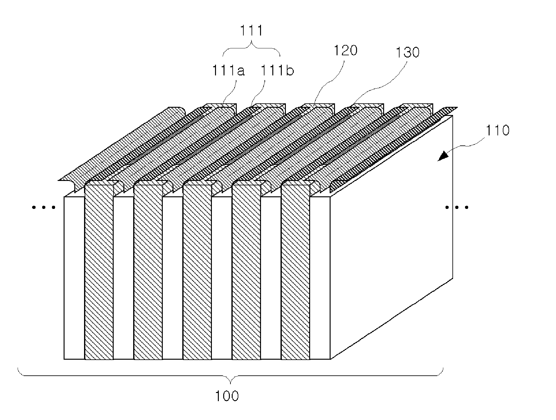
[0028]As shown in FIGS. 6 through 8, support members 120 for supporting the cells 110 are interposed between the cells 110 in such a way that a support member 120 is always between two cells 110. Such a support member is also used in the conventional typical battery, but in the case of the present invention, the width of the support member 120 is comparatively large. Each support member 120 may be made of a metal such as aluminum or, alternatively, it may be made of ...
second embodiment
[0032]Hereinafter, a cell tab connection structure of a battery according to the present invention will be described with reference to FIGS. 9 and 10.
[0033]Like the first embodiment of FIGS. 6 through 8, in the second embodiment, support members 120 are disposed between the cells 110 in such a way that a support member 120 is always between two cells 110. When a direction in which the tabs 111 protrude is called a “tab-side”, a terminal 130 is provided on a tab-side surface of each support member 120. Unlike the first embodiment in which the tabs 111 are bent outwards, in the second embodiment, both side edges 131 of each terminal 130 are bent in the tabside direction. Preferably, each side edge 131 of the terminal 130 is bent at 90°. The bent side edges 131 are brought into close contact with the corresponding tabs 111 and are subsequently joined thereto by resistance welding (S), thus completing the cell tab connection structure of the second embodiment.
[0034]As described above, t...
PUM
 Abstract
Description
Claims
Application Information