Method of Humeral Head Resurfacing and/or Replacement and System for Accomplishing the Method

a technology of humeral head and head, applied in the field of shoulder surgery, can solve the problems of low risk of injury, high incidence of subscapularis dysfunction in anterior deltopectoral approach, severe restricted range of motion of patients vis-à-vis the natural range of motion, etc., and achieve the effect of reducing the risk of nerve damage and avoiding muscle or tendon cutting

Active Publication Date: 2013-08-01
ORTHO INNOVATIONS
View PDF29 Cites 7 Cited by
  • Summary
  • Abstract
  • Description
  • Claims
  • Application Information

AI Technical Summary

Benefits of technology

[0010]The methods and devices described below provide for access to the shoulder joint for shoulder replacement or resurfacing surgery while eliminating the need for cutting of muscle or tendon, thereby limiting the risk of nerve damage inherent in the currently used anterior approach to the surgery. The method entails gaining access to the shoulder joint through a dissected gap between the infraspinatus and teres minor muscles in the back of the shoulder, without cutting through these muscles. The method is facilitated by installation of a jig, which entails establishing a mechanical support in the anatomical neck plane of the proximal humeral head by inserting a pair of pins in the humeral head, within the anatomical neck plane, mounting a frame on the pins which in turn supports a drill guide with its axis perpendicular to the anatomical ne...

Problems solved by technology

However, because muscles and tendons of the shoulder joint are cut, patients often suffer from severely restricted range of motion vis-à-vis the natural range of motion.
Although any surgical exposure runs the low risk of injury to the neurovascular structures during surgical dissection and exposure, the ante...

Method used


Image

  • Method of Humeral Head Resurfacing and/or Replacement and System for Accomplishing the Method
  • Method of Humeral Head Resurfacing and/or Replacement and System for Accomplishing the Method
  • Method of Humeral Head Resurfacing and/or Replacement and System for Accomplishing the Method

Examples


Embodiment Construction

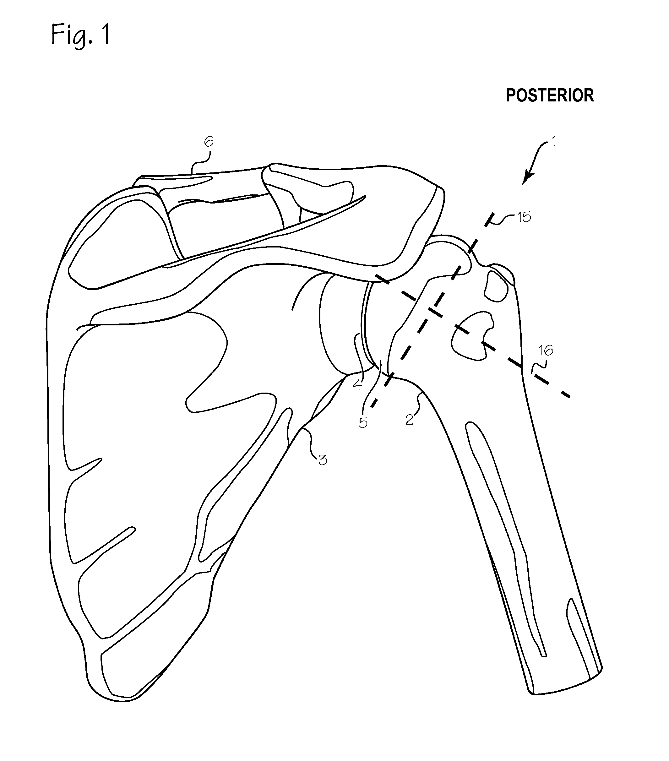
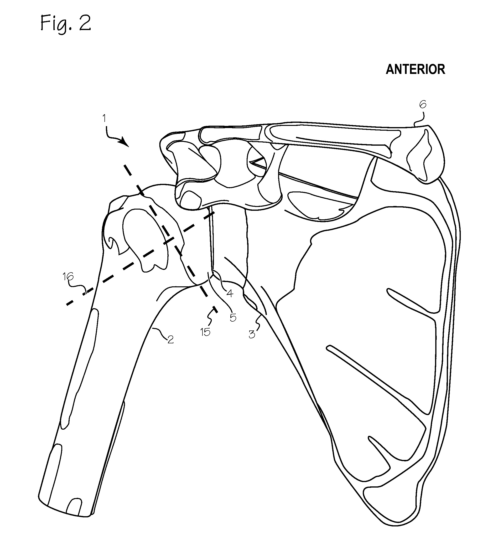
[0030]FIG. 1 is a posterior (back) view of the shoulder 1. The major landmarks include the humerus 2 and the scapula 3, the glenoid fossa 4 and the head 5 of the humerus, the clavicle 6 and the acromonion 7. The humeral head is a roughly semi-spherical mass that fits within a corresponding socket of the glenoid fossa. Together, the humeral head and the glenoid fossa comprise the gleno-humeral joint. FIG. 2 is a corresponding anterior (front) view of the shoulder, showing the same landmarks. The goal of the devices and methods described in this application is to facilitate the remodeling and / or replacement of the surfaces of the humeral head and glenoid fossa. To gain access to the gleno-humeral joint, various layers of tissue (skin, muscle, tendons and ligaments) must be penetrated.

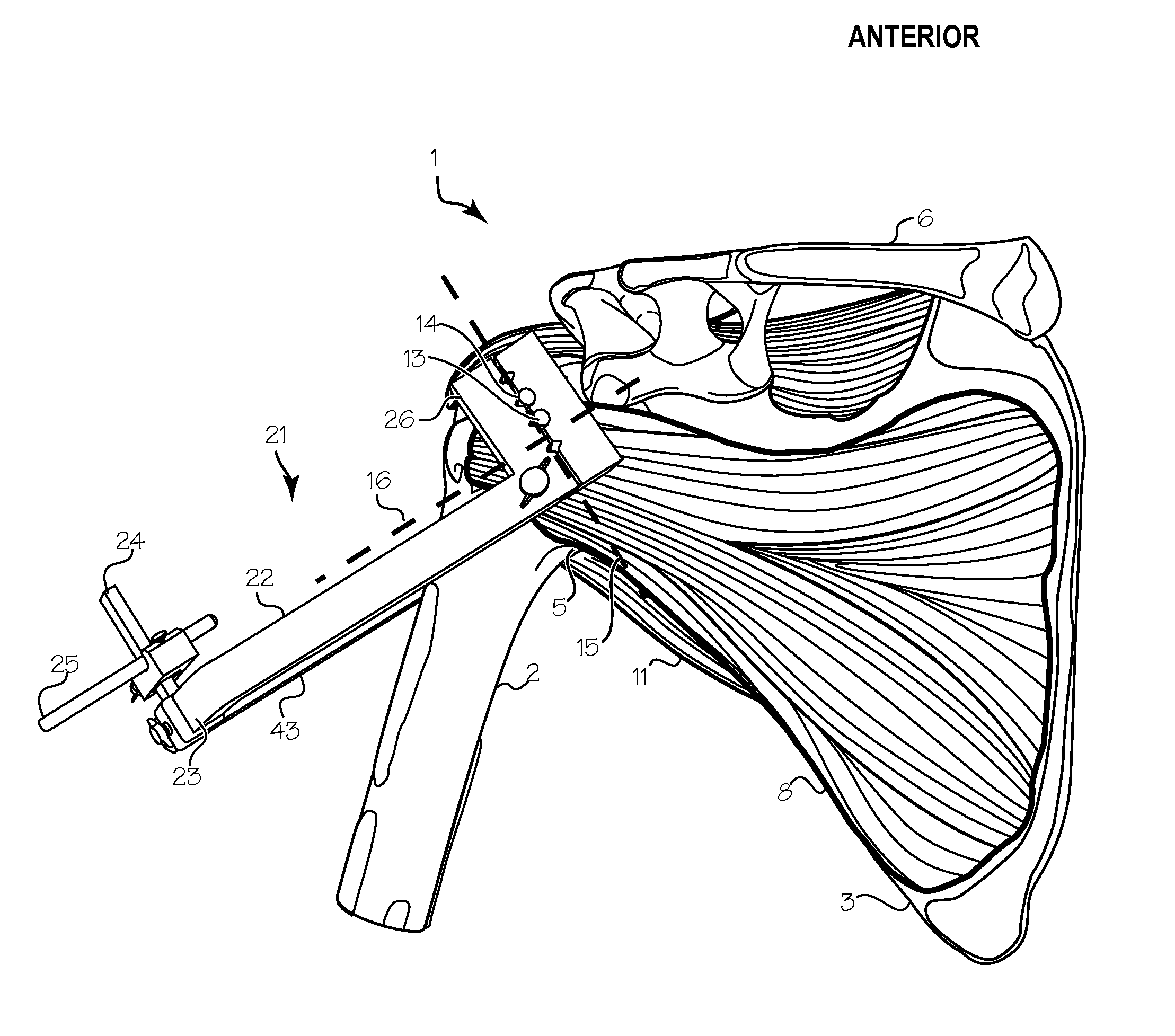
[0031]As shown in FIG. 3, the anterior surface of the gleno-humeral joint is covered by the lateral portion of the subscapularis muscle 8. The axillary nerve, illustrated by the black line 9, runs from ...


PUM


Abstract

A method, and devices for facilitating the method, for shoulder replacement surgery. The method entails establishing a mechanical support in a the anatomical neck plane of the proximal humeral head, fixing a jig to the mechanical support, where the jig supports a drill guide with its axis perpendicular to the anatomical neck plane, adjusting the drill guide it coincide with the axis of the humeral head, drilling a hole through the humeral head for insertion of a shaft which will support and rotate a reaming bit. The reaming bits used to resurface the humeral head and the glenoid fossa are inserted through the back of the patient, through a gap created between two easily separated muscles, rather than through a gap cut through the subscapularis muscle on the front of the joint. A suitable jig is provided to facilitate the method.

Description

[0001]This application claims priority to U.S. Provisional Application 61 / 588,152 filed Jan. 18, 2012.FIELD OF THE INVENTIONS[0002]The inventions described below relate the field of shoulder surgery.BACKGROUND OF THE INVENTIONS[0003]Shoulder replacement surgery and shoulder resurfacing surgery are used to treat severe arthritis or physical damage to the shoulder joint. In shoulder replacement surgeries, the head of the humerus is replaced with a metal ball. The glenoid fossa may also replaced with a plastic socket, covered with a new plastic surface, or ground smooth. When both components are replaced, this is referred to as a total shoulder replacement. When the head is replaced without treatment of the glenoid, this is referred to as a hemiarthroplasty. In shoulder resurfacing, the head of the humerus is ground smooth and covered with a metal cap (a resurfacing hemiarthroplasty), or just ground down. The glenoid fossa may also be ground smooth and covered with a plastic surface.[0...

Claims


Application Information

Patent Timeline
IPC IPC(8): A61B17/17A61B17/16
CPCA61B17/1721A61B2017/1778A61B17/1739A61B17/1684A61B17/16A61B17/1622A61B17/1631A61B17/1659A61B17/175A61B17/1778A61B17/8897A61F2/4014A61F2/4081
Inventor FITZPATRICK, MICHAEL J.
Owner ORTHO INNOVATIONS
Why Eureka
Try Eureka