Engine response adjustment

a technology of engine response and adjustment, applied in the direction of machines/engines, electric control, instruments, etc., can solve the problems of increasing the amount of pedal depression applied, and reducing the ability to maintain a level of vehicle performance. , the effect of reducing the amount of driver effor

Active Publication Date: 2013-08-01
FORD GLOBAL TECH LLC
View PDF16 Cites 26 Cited by
  • Summary
  • Abstract
  • Description
  • Claims
  • Application Information

AI Technical Summary

Benefits of technology

[0004]At least some of the above issues may be addressed by a method for controlling a vehicle engine comprising adjusting a relationship between an operator accelerator pedal depression amount and an engine output torque based on a grade of vehicle travel. In this way, by adjusting the relationship between pedal input and vehicle output using an indication of track elevation, the amount of driver effort required to maintain a level of vehicle performance may be reduced.
[0005]In one example, as the vehicle travels on an incline, the relationship between the pedal input and an engine output torque may be adapted with a higher gain based on the grade of uphill travel. This allows the vehicle to provide a higher output torque for a given pedal depression when climbing an uphill, and reduces the additional pedal movement required by the operator. As another example, when the vehicle travels on a decline, the relationship between the pedal input and an engine output torque may be adapted with a lower gain based on the grade of downhill travel. This allows the vehicle to provide a lower output torque for the given pedal depression when descending a downhill, and reduces the frequent pedal readjustment required by the operator. Similar adjustments may also be made in the presence of headwinds or tailwinds so that the driver's perception of vehicle performance is not degraded. Likewise, adjustments may be made to compensate for the effects of a load on the vehicle, such as when the vehicle is towing or carrying cargo or payloads, since a nominal relationship between the pedal input and the engine output torque may be based on an assumption of an unloaded vehicle.

Problems solved by technology

However, the inventors herein have identified potential issues with such an approach.
As an example, when the vehicle is travelling in regions of varying elevation, the pedal position map of Weber at al. may provide either too little torque or too much torque.
As another example, even if the vehicle is not travelling on an uphill or downhill grade, the same issues may arise in the presence of headwinds or tailwinds.
During all such operating conditions, the operator may need to be extra attentive and may need to frequently readjust the amount of pedal depression applied without knowing how much is necessary to maintain a desired vehicle speed (or vehicle acceleration).
As such, this may degrade the drive feel and lead to operator dissatisfaction.

Method used


Image

  • Engine response adjustment
  • Engine response adjustment
  • Engine response adjustment

Examples


Embodiment Construction

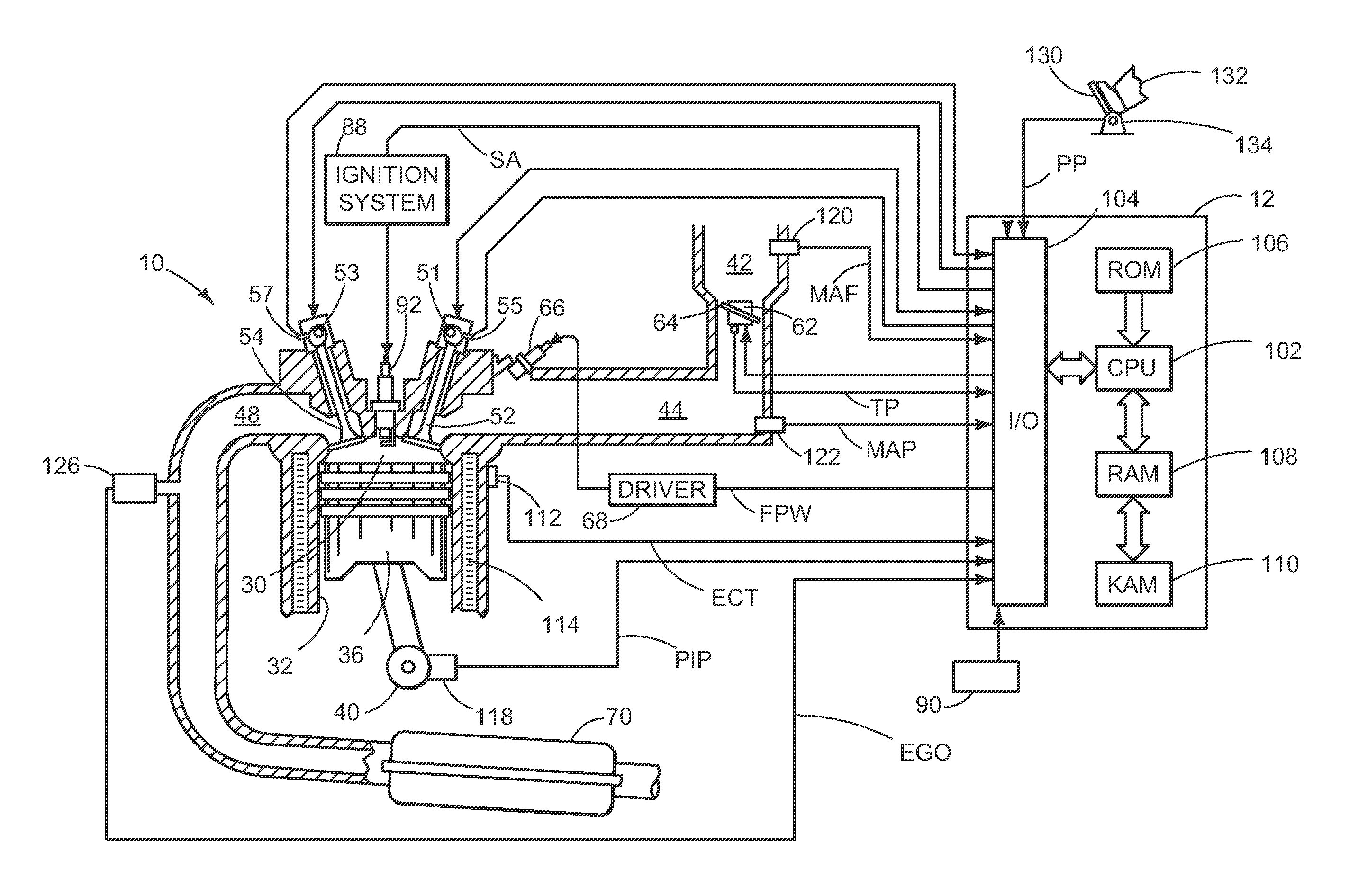
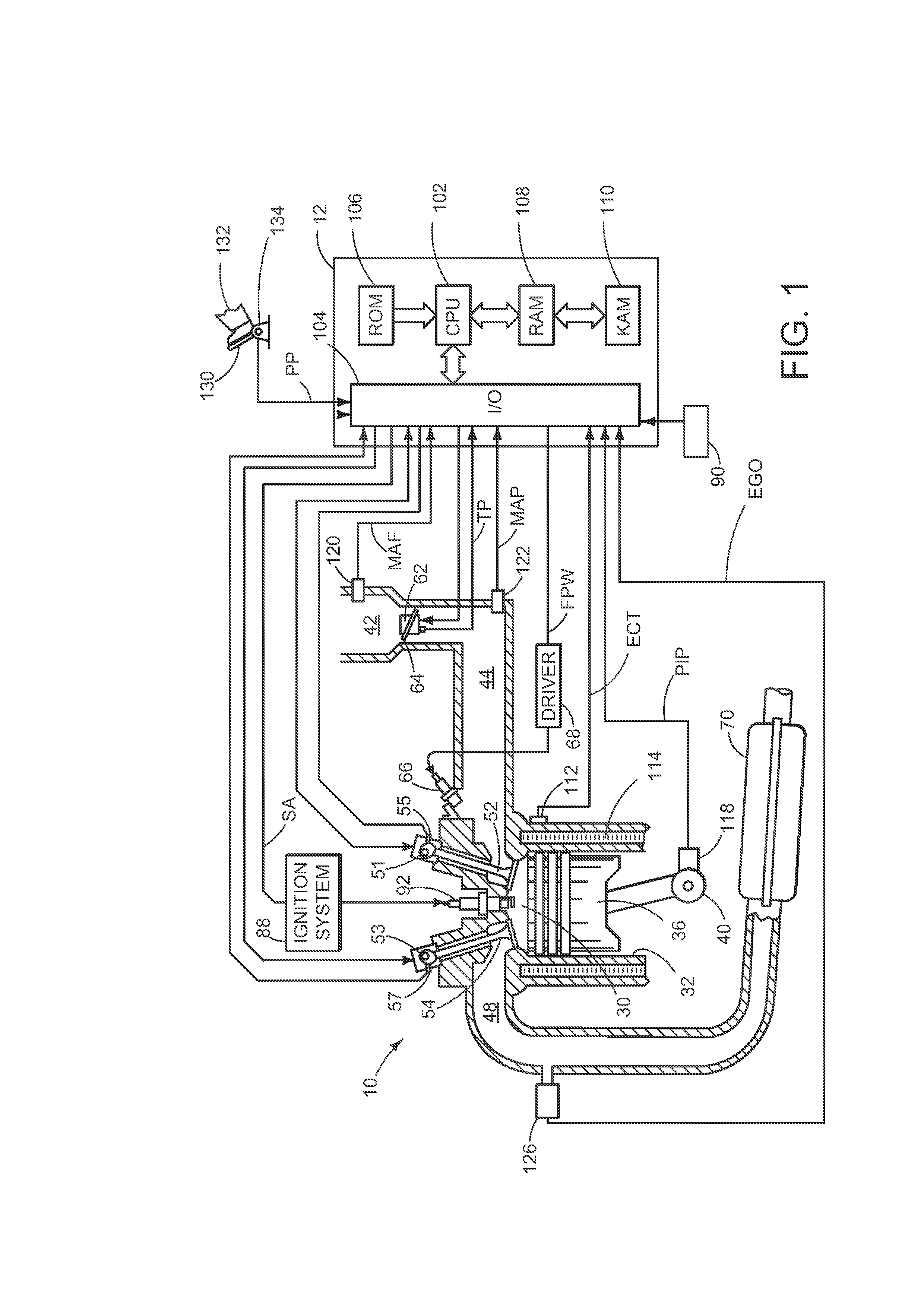
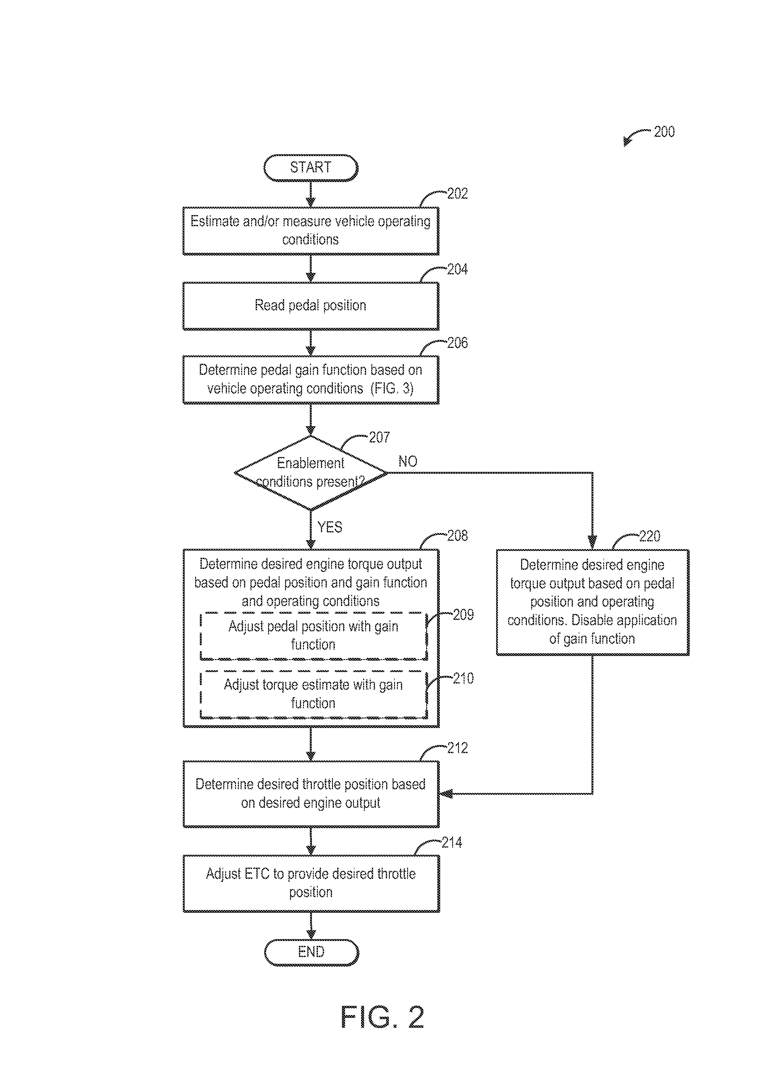
[0016]The present application describes methods and systems for adjusting the relationship between an accelerator pedal signal and engine output torque in the engine system of FIG. 1. An engine controller may map an accelerator pedal signal to an engine output torque and further adjust the mapping with an adaptation term that is based on selected vehicle operating conditions. The controller may be configured to perform a control routine, such as the example routines of FIGS. 2-3, to determine a gain function based on vehicle operating conditions, such as vehicle road grade, the presence of headwinds or tailwinds, as well as a load being carried or towed by the vehicle. Example gain function adjustments are described herein with reference to the graphs of FIGS. 4A-B and 5A-B. In some embodiments, the controller may apply a grade compensation algorithm (FIG. 7) so that as the road elevation varies, the pedal position of the operator may be maintained as close to a nominal pedal positi...


PUM


Abstract

Methods and systems are provided for adjusting an engine output delivered in response to an operator pedal actuation based at least on a grade of vehicle travel. During uphill travel, in the presence of headwinds, and/or in the presence of a vehicle payload, the output may be increased while during downhill travel or in the presence of tailwinds, the output may be decreased. In this way, driver fatigue during travel over varying elevations, varying ambient conditions, and varying loads can be reduced.

Description

BACKGROUND AND SUMMARY[0001]Vehicles systems receive various operator commands in order to facilitate operator control of the powertrain, including an accelerator pedal position input. Further, the relationship between the amount of pedal depression by the operator and the powertrain response can be tuned to provide different speed and torque controls.[0002]One example approach for adjusting a pedal position map is provided by Weber at al. in U.S. Pat. No. 6,654,677. Therein, a powertrain controller varies the mapping of an accelerator pedal position to an electronic throttle angle based on the vehicle speed to improve operator control over vehicle speed, torque output, and acceleration. In particular, at lower vehicle speeds, the pedal position is mapped to the electronic throttle angle with focus on providing acceleration control, while at higher vehicle speeds, the pedal position is mapped to the electronic throttle angle with focus on controlling vehicle speeds.[0003]However, th...

Claims


Application Information

Patent Timeline
Patent Type & Authority Applications(United States)
IPC IPC(8): F02D28/00
CPCF02D41/32Y02T10/42F02D13/0249F02D41/0002F02D41/0032F02D41/005F02D2041/001F02D2041/1422F02D2200/1002F02D2200/50F02D2200/602F02D2200/70F02D2200/701F02D2250/18B60K26/04B60K2026/046B60W2550/142F02D11/105B60W2552/15Y02T10/40F02D13/0203F02D28/00F02D2009/0213
Inventor SZWABOWSKI, STEVEN JOSEPHHODOREK, CRAIG THOMAS
Owner FORD GLOBAL TECH LLC
Why Eureka
Try Eureka