System and Method for Mitigating the Impact of Branch Misprediction When Exiting Spin Loops

a technology of branch misprediction and spin loop, which is applied in the field of system and method for mitigating the impact of branch misprediction when exiting spin loop, and can solve problems such as significant performance loss, stalling of microprocessors, and stalling due to misprediction

Active Publication Date: 2013-08-01
ORACLE INT CORP
View PDF12 Cites 68 Cited by
  • Summary
  • Abstract
  • Description
  • Claims
  • Application Information

AI Technical Summary

Benefits of technology

[0006]In response to identifying the loop and the conditional branch type instruction that specifies its exit condition, the system may influence or override a prediction made by a dynamic branch predictor, resulting in a prediction that the exit condition will be met and that the loop will be exited, regardless of any observed branch behavior for the conditional branch type instruction. This prediction may cause the processor to mispredict the branch path while looping (incurring a delay due to the misprediction on each successive loop iteration), but to quickly respond when the exit condition is met, transferring the execution flow to the exit path for the busy-wait loop without incurring a misprediction delay.

Problems solved by technology

Because conditional branch type instructions are control transfer instructions (CTIs), they can cause microprocessors to stall because the instructions to be executed after the control transfer instructions are not known until the control transfer instruction is executed.
These stalls can result in significant loss of performance.
However, each time the branch predictor mispredicts the direction and / or target of a conditional branch type instruction, there is a stall due to the misprediction.
The delay due to such a stall can be significant, depending on the processor and / or its pipelining (e.g., the depth and implementation of the pipeline).

Method used


Image

  • System and Method for Mitigating the Impact of Branch Misprediction When Exiting Spin Loops
  • System and Method for Mitigating the Impact of Branch Misprediction When Exiting Spin Loops
  • System and Method for Mitigating the Impact of Branch Misprediction When Exiting Spin Loops

Examples


Embodiment Construction

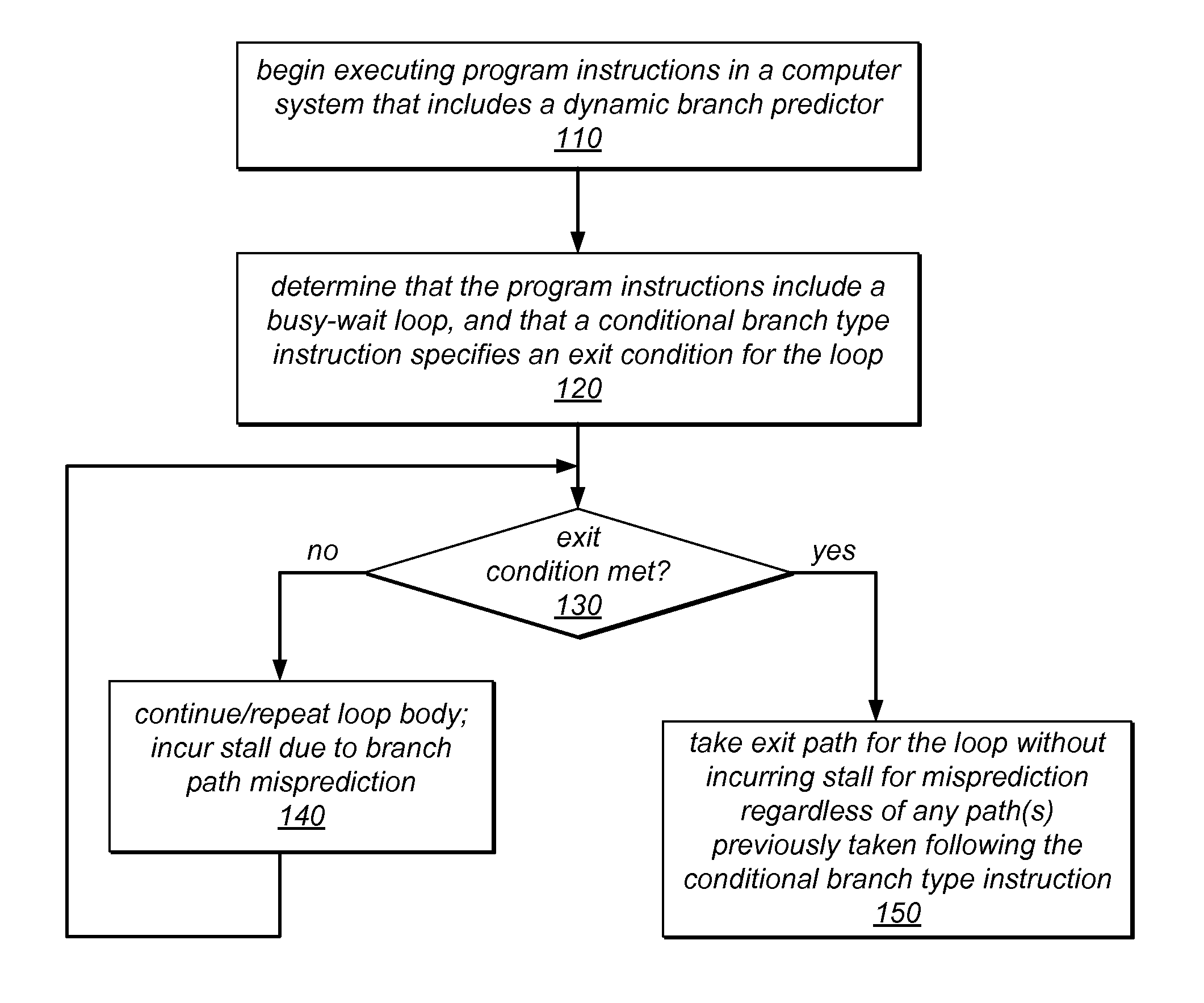
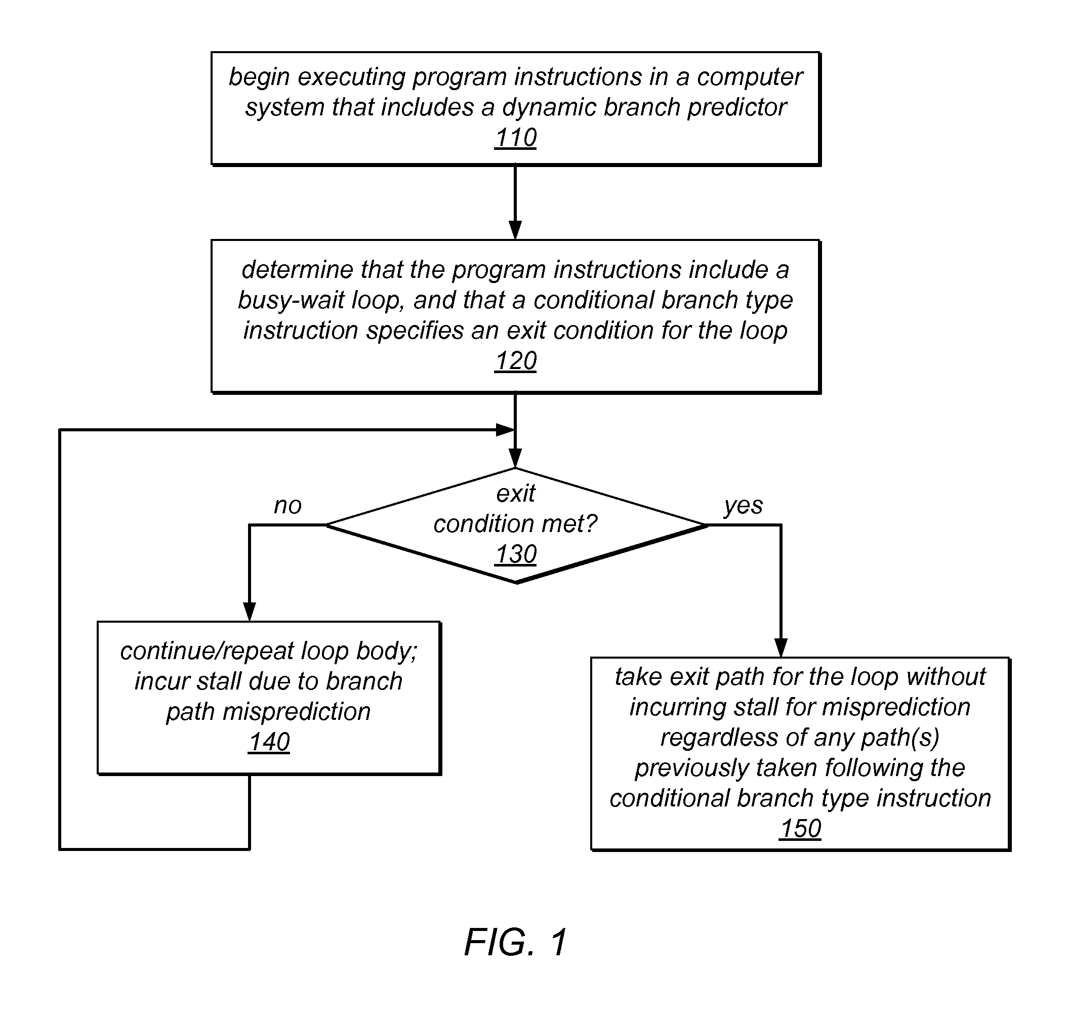
[0019]In various computing systems, spin loops (which may also be referred to herein as busy-wait loops) may be used for inter-thread communication. For example, they may be employed in a computer system to implement waiting for an inter-thread communication event to occur, or to implement waiting for a lock on a shared resource or critical section of code to become available. If program execution encounters one of these spin loops (or busy-wait loops), it may enter the loop and wait for a specified exit condition to be met. Once the exit condition is met, the execution flow may be transferred out of the loop (e.g., by branching). In some embodiments, conditional branch type instructions may be used for controlling the flow of an application that includes various types of spinning / waiting constructs. For example, a conditional branch type instruction may specify a condition that when met causes the program to exit a spin loop.

[0020]As used herein, the term “conditional branch type i...


PUM


Abstract

A computer system may recognize a busy-wait loop in program instructions at compile time and/or may recognize busy-wait looping behavior during execution of program instructions. The system may recognize that an exit condition for a busy-wait loop is specified by a conditional branch type instruction in the program instructions. In response to identifying the loop and the conditional branch type instruction that specifies its exit condition, the system may influence or override a prediction made by a dynamic branch predictor, resulting in a prediction that the exit condition will be met and that the loop will be exited regardless of any observed branch behavior for the conditional branch type instruction. The looping instructions may implement waiting for an inter-thread communication event to occur or for a lock to become available. When the exit condition is met, the loop may be exited without incurring a misprediction delay.

Description

BACKGROUNDDescription of the Related Art[0001]In computer programming, busy-waiting (or spinning) is a technique in which a thread or process repeatedly checks to see if a condition is true or an event has taken place before advancing past the point of the busy-wait loop. For example, a busy-wait loop may be used to wait for a lock that controls access to a shared resource or critical section of code to be released or acquired. In multithreaded applications, busy-waiting is sometimes used for inter-thread communication or coordination, with one thread spinning until it receives an indication that another thread has performed a particular task or updated a shared memory location (e.g., with a specific value). The execution flow for a busy-wait loop is often controlled by a conditional branch type instruction that checks for a desired condition or event indication. When the condition is met or the indication is received, the execution flow is transferred out of the loop.[0002]Because ...

Claims


Application Information

Patent Timeline
Patent Type & Authority Applications(United States)
IPC IPC(8): G06F9/38
CPCG06F9/30079G06F9/325G06F9/3848G06F9/3846G06F9/30058
Inventor DICE, DAVIDMOIR, MARK S.
Owner ORACLE INT CORP
Why Eureka
Try Eureka