
Filter device and filter system

a filter device and filter system technology, applied in the direction of dispersed particle filtration, isotope separation, non-fuel substance addition to fuel, etc., can solve the problem of fuel tank pressure rising, and achieve the effect of improving filtering performance, robustness, and long-term stability

Inactive Publication Date: 2015-06-18
DR ING H C F PORSCHE AG
View PDF5 Cites 2 Cited by
  • Summary
  • Abstract
  • Description
  • Claims
  • Application Information

AI Technical Summary

Benefits of technology

The patent text describes a filter device that can be easily adapted to meet current regulations regarding filtering capacity. The device can be used in different vehicles and has a large cross section for gas flow, allowing for a higher filtering capacity. Additionally, a filling element can be added to provide stability and protection against vibration and impact. The device can be produced with a monolithic filter element or a filling element depending on the specific needs.

Problems solved by technology

Pressure in the fuel tank may rise due to heating, for example, because of solar insolation.

Method used


Image

  • Filter device and filter system
  • Filter device and filter system

Examples


Embodiment Construction

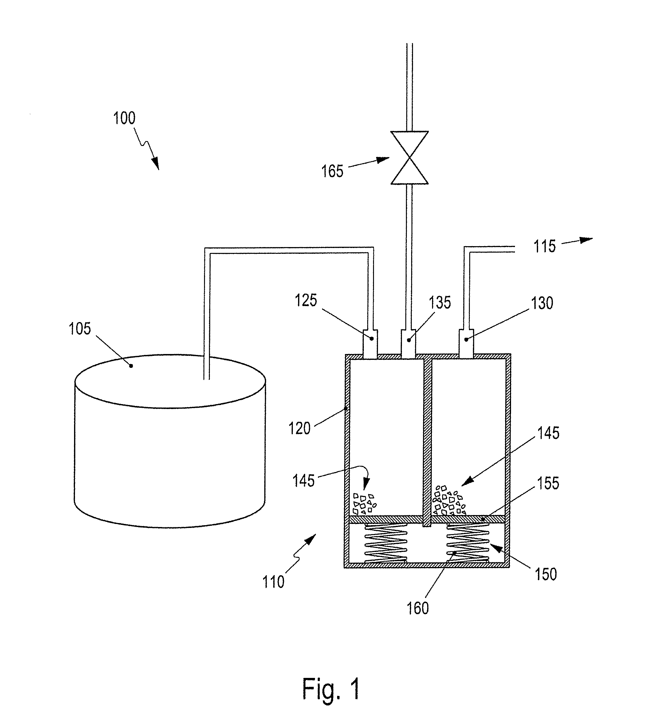
[0028]FIG. 1 is a schematic illustration of a fuel system 100 for use on board a motor vehicle. The fuel system 100 comprises a fuel tank 105 for liquid fuel and a filter device 110. The fuel tank 105 customarily is filled partially with the liquid fuel. A remaining residual volume is filled with a gas that customarily is formed by ambient air in which portions of the fuels are dissolved or are accumulated in the form of fuel vapor. The concentration of fuel in the gas is dependent on a vapor pressure of the fuel, which is dependent on a temperature of the fuel. If the temperature in the region of the fuel tank 105 rises, the gas and the fuel expand, thus producing a positive pressure. To dissipate the positive pressure, a portion of the gas is released through the filter device 110 into an environment 115.

[0029]The filter device 110 comprises a chamber 120, a first port 125 and a second port 130. The ports 125 and 130 lead into the chamber 120 which is otherwise closed in a fluid-t...


PUM

PropertyMeasurementUnit
heightaaaaaaaaaa
structureaaaaaaaaaa
volumeaaaaaaaaaa

Abstract

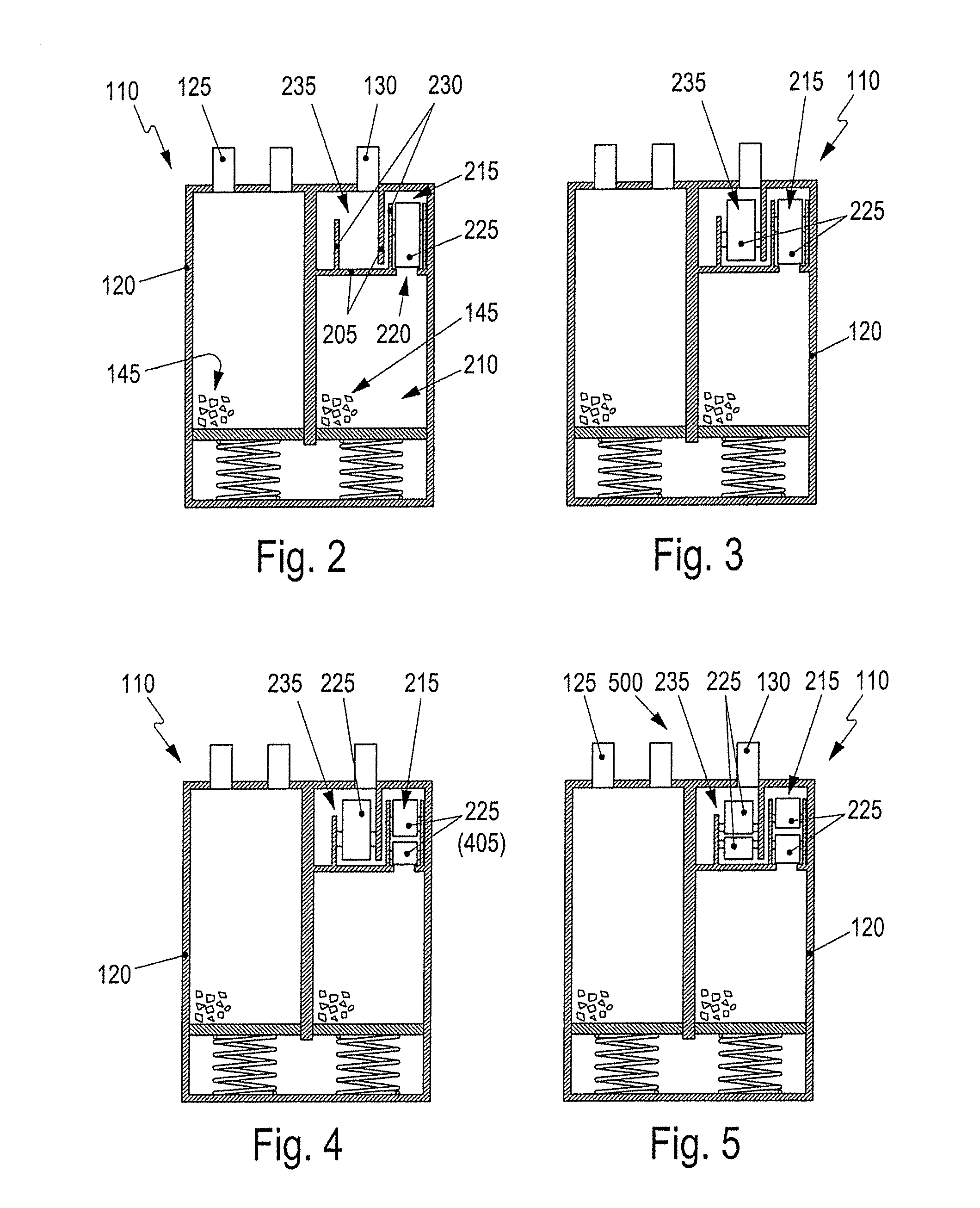
A filter device for the exchange of gas between the fuel tank for liquid fuel and an environment has a chamber sealed in a fluid-tight manner. A first port leads into the chamber for fluid connection to the fuel tank. A second port into leads the chamber for fluid connection to the environment. A granular filter material is in the chamber. The chamber is designed for optionally accommodating a monolithic filter element in addition to the granular filter material.

Description

CROSS REFERENCE TO RELATED APPLICATION[0001]This application claims priority under 35 USC 119 to German Patent Appl. No. 10 2013 114 020.3 filed on Dec. 13, 2013, the entire disclosure of which is incorporated herein by reference.BACKGROUND[0002]1. Field of the Invention[0003]The invention relates to a filter device and to a filter system for an exchange of gas between a fuel tank for liquid fuel and an environment.[0004]2. Description of the Related Art[0005]A fuel tank for liquid fuel in a motor vehicle is connected to an environment by a filter device. The tank customarily contains the liquid fuel and a volume of gas in which portions of the fuel are dissolved. Pressure in the fuel tank may rise due to heating, for example, because of solar insolation. Thus, the contents expand and the gas flows through the filter device and into the environment. The filter device is designed to retain at least a proportion of the fuel dissolved in the gas. For this purpose, a filter material for...

Claims


Application Information

Patent Timeline
Patent Type & Authority Applications(United States)
IPC IPC(8): B01D53/04B01D46/24
CPCB01D53/0407B01D46/2418B01D2259/4516B01D2257/702B01D2253/102B01D2253/3425F02M25/0854
Inventor MENKE, ANDREASESSIG, ULRICHBOLZHAUSER, UWE
Owner DR ING H C F PORSCHE AG
Learn More