Method of manufacturing a turbine blade, system for manufacturing a turbine blade, intermediate member for manufacturing a turbine blade, and turbine blade manufactured by means of the aforementioned method

a technology for wind turbines and turbine blades, which is applied in the field of manufacturing turbine blades, can solve the problems of cumbersome and laborious, and the web packing involves a significant amount of expensive and time-consuming manual work, and achieves the effects of reducing the amount of manual work, reducing labor and time, and avoiding the effect of completely preventing the web packing

Inactive Publication Date: 2013-08-08
SIEMENS AG
View PDF0 Cites 3 Cited by
  • Summary
  • Abstract
  • Description
  • Claims
  • Application Information

AI Technical Summary

Benefits of technology

[0010]The described method allows for directly arranging the elongate core surrounded by the textile structure in the mold. Thereby, the labor, time and cost intensive step of web packing, which involves arranging and adjusting a large number of individual fiber mats or webs in the mold, can be replaced with the simple step of arranging a pre-fabricated unit or structure constituted by an elongate core surrounded by a textile structure in the mold.
[0011]It should be noted that the described method may also be used in combination with traditional web packing, in the sense that some further fiber material is manually arranged in the mold together with the elongate core surrounded by the textile structure. In this case, the web packing is not completely prevented, but the associated amount of manual work can nevertheless be significantly reduced in comparison to pure web packing.
[0012]The elongate core is preferably made from a flexible material. Thereby, if a vacuum is produced within the mold after the elongate core surrounded by the textile structure has been placed therein, the flexible core may expand and thereby press the textile structure against the mold such that a close fit can be obtained. This effect can also be achieved or further enhanced by inflating the elongate core with a suitable fluid, such as a gas, or by inserting a relatively hard mold core body into the elongate core.
[0013]The textile structure is preferably a complex structure consisting of several different fiber materials, such as glass fibers, carbon fibers, natural fibers, and spacer or core materials, such as balsa wood or PVC foam. The textile structure may appear as forming a fluffy tubular or sock-like structure embedding the various aforementioned materials around the elongate core. The pre-manufactured textile structure preferably represents at least a part of the load carrying element of the turbine blade. The textile structure may be pre-hardened such that it is easier to handle, e.g. during arrangement of the textile structure within the mold.

Problems solved by technology

The abovementioned processes for manufacturing a turbine blade all include a cumbersome and labor intensive step of arranging the various laminate materials, such as dry glass fibers and / or pre-treated materials, in the mold prior to injection of a suitable liquid (e.g. epoxy) for curing.
As can be seen, the web packing necessarily involves a significant amount of expensive and time consuming manual work in order to meet the required quality standard.

Method used


Image

  • Method of manufacturing a turbine blade, system for manufacturing a turbine blade, intermediate member for manufacturing a turbine blade, and turbine blade manufactured by means of the aforementioned method
  • Method of manufacturing a turbine blade, system for manufacturing a turbine blade, intermediate member for manufacturing a turbine blade, and turbine blade manufactured by means of the aforementioned method
  • Method of manufacturing a turbine blade, system for manufacturing a turbine blade, intermediate member for manufacturing a turbine blade, and turbine blade manufactured by means of the aforementioned method

Examples


Embodiment Construction

[0051]The illustration in the drawing is schematically. It is noted that in different figures, similar or identical elements are provided with the same reference signs or with reference signs, which are different from the corresponding reference signs only within the first digit.

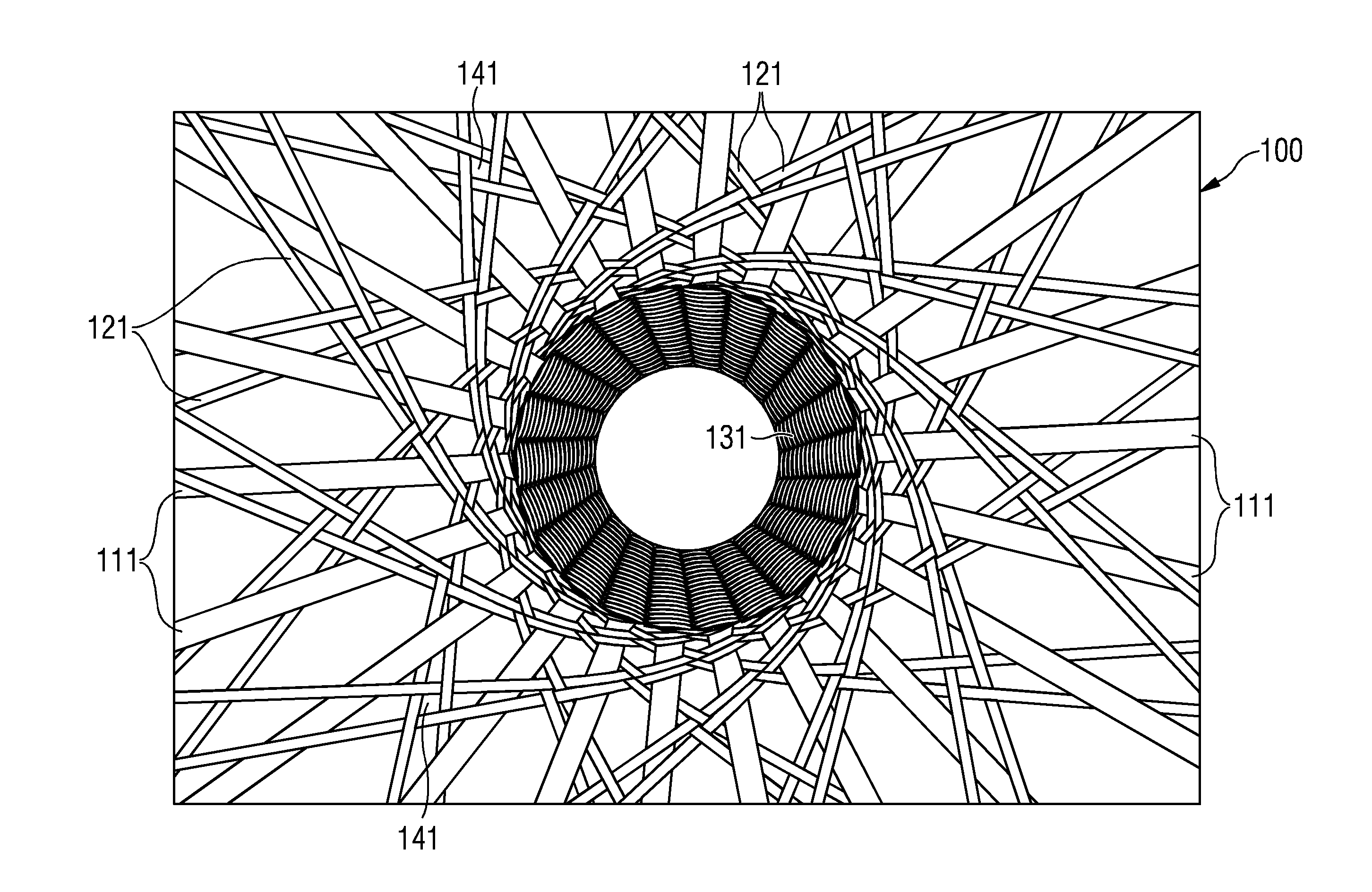
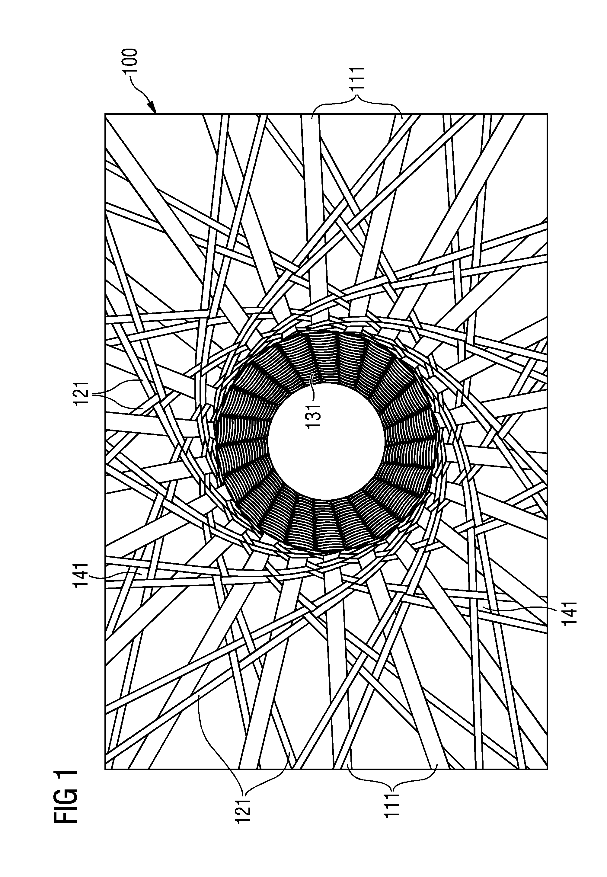
[0052]FIG. 1 shows a temporary state of a textile structure 100 during production in accordance with an embodiment. The central part of FIG. 1 shows a finished woven tubular textile matrix structure 131 having a substantially circular cross-section. The textile structure may be formed around a core, such as an elongate core (not shown).

[0053]In the outer parts of FIG. 1, the various fibers or threads 111 and 121 which are woven into the finished textile matrix structure 131 can be seen. In particular, FIG. 1 shows a first kind of fibers 111 (first fibers 111) and a second kind of fibers 121 (second fibers 121). In the present embodiment, the first fibers 111 are functional fibers or threads, which are chosen...


PUM

PropertyMeasurementUnit
textile structureaaaaaaaaaa
circumferenceaaaaaaaaaa
shapeaaaaaaaaaa

Abstract

A method of manufacturing a turbine blade is provided. The described method includes providing an elongate core, surrounding the elongate core with a textile structure, arranging the elongate core surrounded by the textile structure in a mold, pressing at least a part of the textile structure against the mold, and injecting a curing agent into the mold to interact with the textile structure, thereby forming the turbine blade. Also, a system and an intermediate member for manufacturing a turbine blade by means of the described method is provided.

Description

CROSS REFERENCE TO RELATED APPLICATIONS[0001]This application claims priority of European Patent Office application No. 12154226.0 EP filed Feb. 7, 2012. All of the applications are incorporated by reference herein in their entirety.FIELD OF INVENTION[0002]The present invention relates to the field of manufacturing turbine blades, more particularly to manufacturing blades for wind turbines and / or water turbines.ART BACKGROUND[0003]Turbine blades are typically produced by means of a casting process. Several suitable casting processes are known. For example, it is known to produce a blade for a wind turbine by separately molding two or more parts, such as an upper and a lower half, and then gluing the separately molded parts together to form the final blade. Further, as described e.g. in EP 1 310 351 A1, manufacturing methods have been developed which make it possible to produce a wind turbine blade as one single molded piece. The latter methods are also known as integral blade moldin...

Claims


Application Information

Patent Timeline
Patent Type & Authority Applications(United States)
IPC IPC(8): B29C70/44
CPCB29C70/446B29L2031/082Y10T29/49337Y10T428/239B29C70/443
Inventor STIESDAL, HENRIKWOLF, ERIK
Owner SIEMENS AG
Why Eureka
Try Eureka