System and method for expansion of field of view in a vision system

a vision system and field of view technology, applied in the field of vision systems, can solve the problems of affecting the field of view of single readers, and readers that miss ids outside the field of view, so as to avoid image distortion

Active Publication Date: 2013-08-08
COGNEX CORP
View PDF0 Cites 28 Cited by
  • Summary
  • Abstract
  • Description
  • Claims
  • Application Information

AI Technical Summary

Benefits of technology

[0006]This invention overcomes disadvantages of the prior art by providing a system and method for expanding the field of view of a vision system camera assembly that can be employed as an ID reader such that the field of view is generally free of loss of normal resolution of a camera assembly sensor, and ensures that features of interest, such as IDs, are fully imaged across the entire expanded field. In an embodiment a field of view expander (FOVE) includes outer mirrors directed to receive light from different widthwise portions of a scene, which can be a moving line of objects. The outer mirrors thereafter direct the light to associated vertically tilted inner mirrors of a beam spli

Problems solved by technology

Thus, the field of view of a single reader, particularly in with widthwise direction (perpendicular to line motion) is often limited.
Where an object and/or the line is relatively wide, the lens and sensor of a single ID reader may not have sufficient field of view in the widthwise direction to cover the entire width of the line while maintaining needed resolution for accurate imaging and decoding of IDs.
Failure to image the full width can cause the reader to miss IDs that are outside of the

Method used


Image

  • System and method for expansion of field of view in a vision system
  • System and method for expansion of field of view in a vision system
  • System and method for expansion of field of view in a vision system

Examples


Embodiment Construction

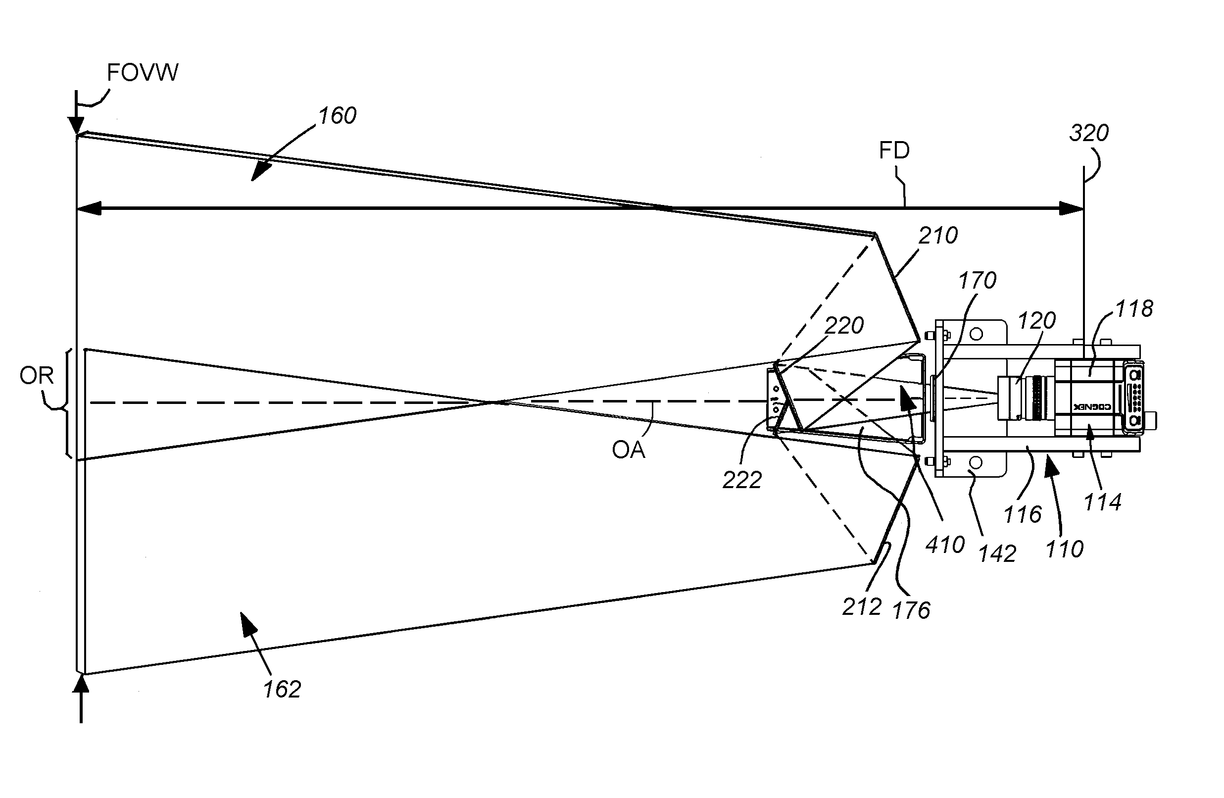
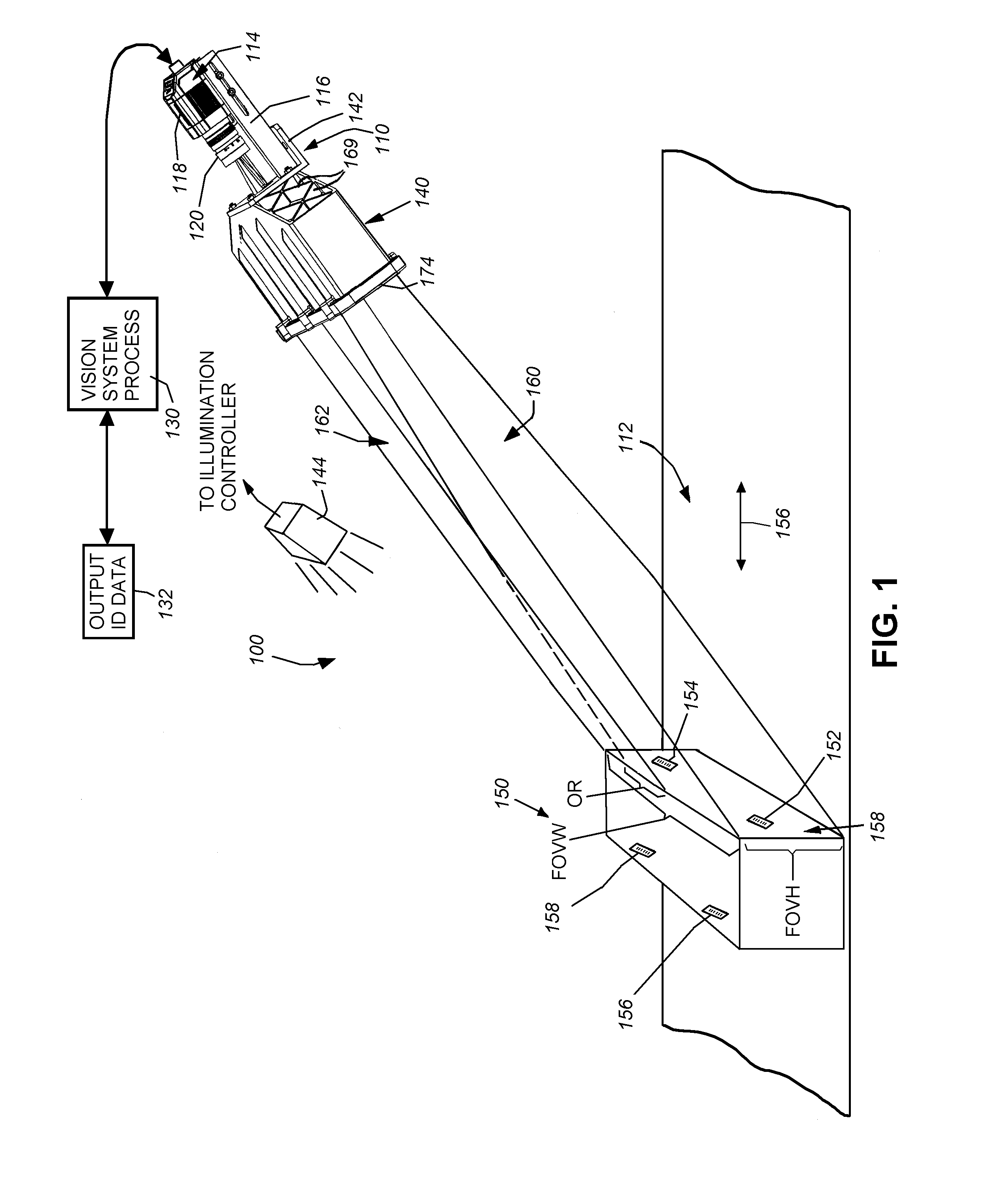
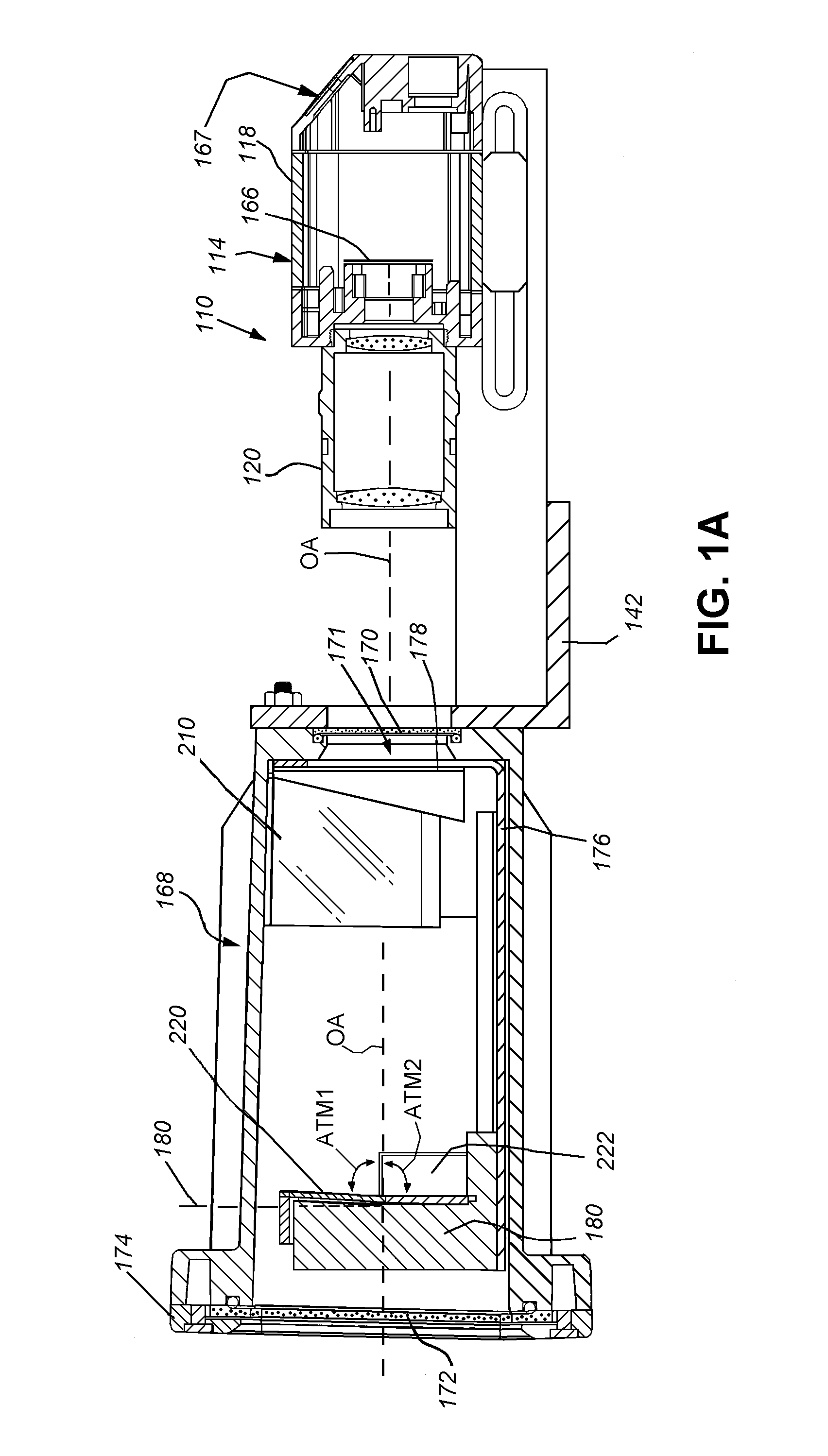
[0024]FIG. 1 shows a vision system arrangement 100 in which a vision system or ID reader assembly 110 oriented at an acute angle with respect to a moving line represented by a conveyor 112. The vision system 110 includes a camera assembly 114 adjustably mounted in a frame 116. The camera assembly includes the camera base 118 and a lens 120. A variety of camera implementations can be employed in alternate embodiments. In an embodiment, the base 118 includes an internal sensor (described below), having a pixel array for acquiring grayscale of color image data. The size of the array is highly variable. For example, the array can be a conventional rectangular (roughly square) array having a size of 1024×768 pixels. In alternate embodiments, other array sizes, including, but not limited to, 2048×384 or 2048×768 pixels can be employed. The camera base 118 can include an internal vision processor and ID (barcode) decoding circuit. Alternatively, the camera can transmit raw image data to a ...


PUM


Abstract

This invention provides a system and method for expanding the field of view of a vision system camera assembly such that the field of view is generally free of loss of normal resolution across the entire expanded field. A field of view expander includes outer mirrors that receive light from different portions of a scene. The outer mirrors direct light to tilted inner mirrors of a beam splitter that directs the light aligned with a camera axis to avoid image distortion. The inner mirrors each direct the light from each outer mirror into a strip on the sensor, and the system searches features. The adjacent fields of view include overlap regions sized and arranged to ensure a centralized feature appears fully in at least one strip. Alternatively, a moving mirror changes position between acquired image frames so that a full width of the scene is imaged in successive frames.

Description

FIELD OF THE INVENTION[0001]This invention relates to vision systems, and more particularly to systems and methods for expanding the field of view of a vision system camera lens.BACKGROUND OF THE INVENTION[0002]Vision systems that perform measurement, inspection, alignment of objects and / or decoding of symbology (e.g. bar codes—also termed “IDs”) are used in a wide range of applications and industries. These systems are based around the use of an image sensor, which acquires images (typically grayscale or color, and in one, two or three dimensions) of the subject or object, and processes these acquired images using an on-board or interconnected vision system processor. The processor generally includes both processing hardware and non-transitory computer-readable program instructions that perform one or more vision system processes to generate a desired output based upon the image's processed information. This image information is typically provided within an array of image pixels ea...

Claims


Application Information

Patent Timeline
IPC IPC(8): G06K7/10H04N5/225G02B27/14
CPCG06K7/1491H04N5/2254H04N5/2259G03B17/565G06K7/10831G02B27/1066G02B27/14H04N5/23238H04N23/58H04N23/55H04N23/60H04N23/698
Inventor NUNNINK, LAURENSGERST, III, CARL W.EQUITZ, WILLIAM H.ENGLE, MATTHEW D.
Owner COGNEX CORP
Why Eureka
Try Eureka