
Ceramic electronic component

Active Publication Date: 2013-08-08
MURATA MFG CO LTD
View PDF15 Cites 14 Cited by
  • Summary
  • Abstract
  • Description
  • Claims
  • Application Information

AI Technical Summary

Benefits of technology

The present invention provides a ceramic electronic component that has excellent moisture resistance while maintaining a thin external electrode. The ceramic part can be plated quickly and efficiently, with the plating film growing in a way that reduces the size of the component.

Problems solved by technology

However, because the electrically conductive paste used in forming the sintered metal film has high viscosity, the thickness of the resultant sintered metal film becomes large.
In this case, a plating solution may enter the ceramic body through the site where the reaction layer is formed, which may cause a problem of a decrease in mechanical strength of the ceramic body and a problem of deterioration in reliability of moisture resistance thereof.
In addition, the high baking temperature causes the precipitation of the glass component on the surface of the sintered metal film, i.e., glass floating, which presents another problem of difficulty in forming a plating film on the surface of the sintered metal film.
Therefore, problems of a decrease in mechanical strength and deterioration in reliability of moisture resistance due to the formation of the reaction layer are less likely to occur.
This presents a problem of the plating solution entering into the ceramic body through exposed portions of the internal electrodes.
Thus, the resultant ceramic electronic component may have decreased moisture resistance.
Furthermore, when the external electrode is formed only of a plating film, the plating film is not chemically but only physically bound to the ceramic body, so that the adhesion between the plating film and the ceramic body will be poor.
As a result, when the ceramic electronic component is in use, moisture or the like is likely to enter the ceramic body from between the plating film and the ceramic body.
Also in this view, the resultant ceramic electronic component may have decreased moisture resistance.

Method used


Image

  • Ceramic electronic component
  • Ceramic electronic component
  • Ceramic electronic component

Examples


first preferred embodiment

[0044]Hereinafter, preferred embodiments of the present invention will be described. However, the following preferred embodiments are merely illustrative. The present invention is not intended to be limited to the following preferred embodiments.

[0045]Throughout the drawings to which the preferred embodiments and the like refer, elements having substantially the same functions will be referred to by the same reference signs. The drawings to which the preferred embodiments and the like refer are schematically illustrated and, therefore, the dimensional ratios and the like of elements illustrated in the drawings may be different from those of the actual elements. Different drawings may have different dimensional ratios and the like of the elements. Dimensional ratios and the like of specific objects should be determined in consideration of the following descriptions.

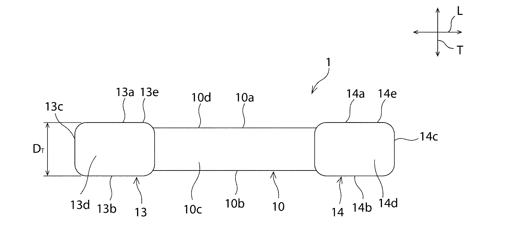
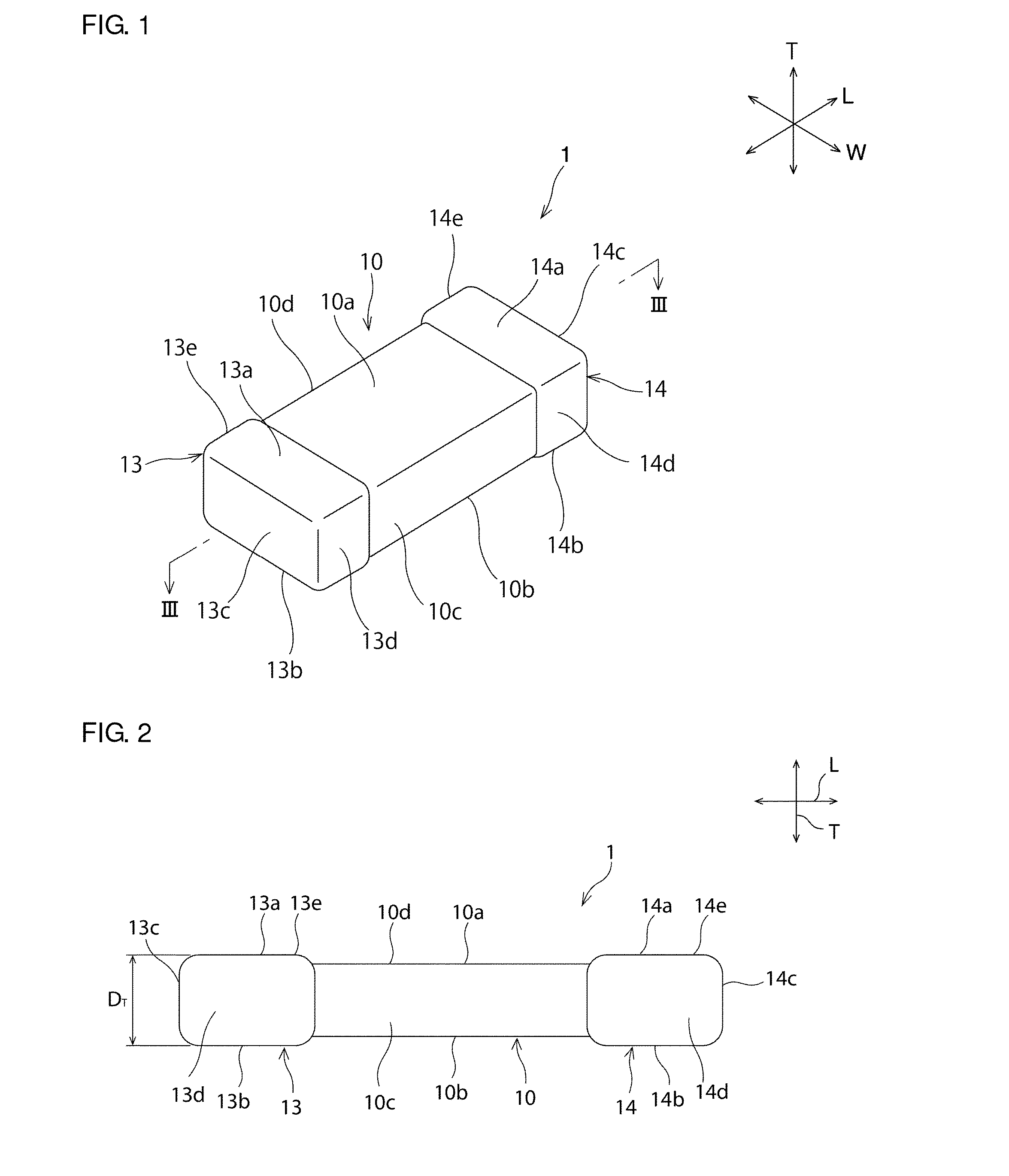
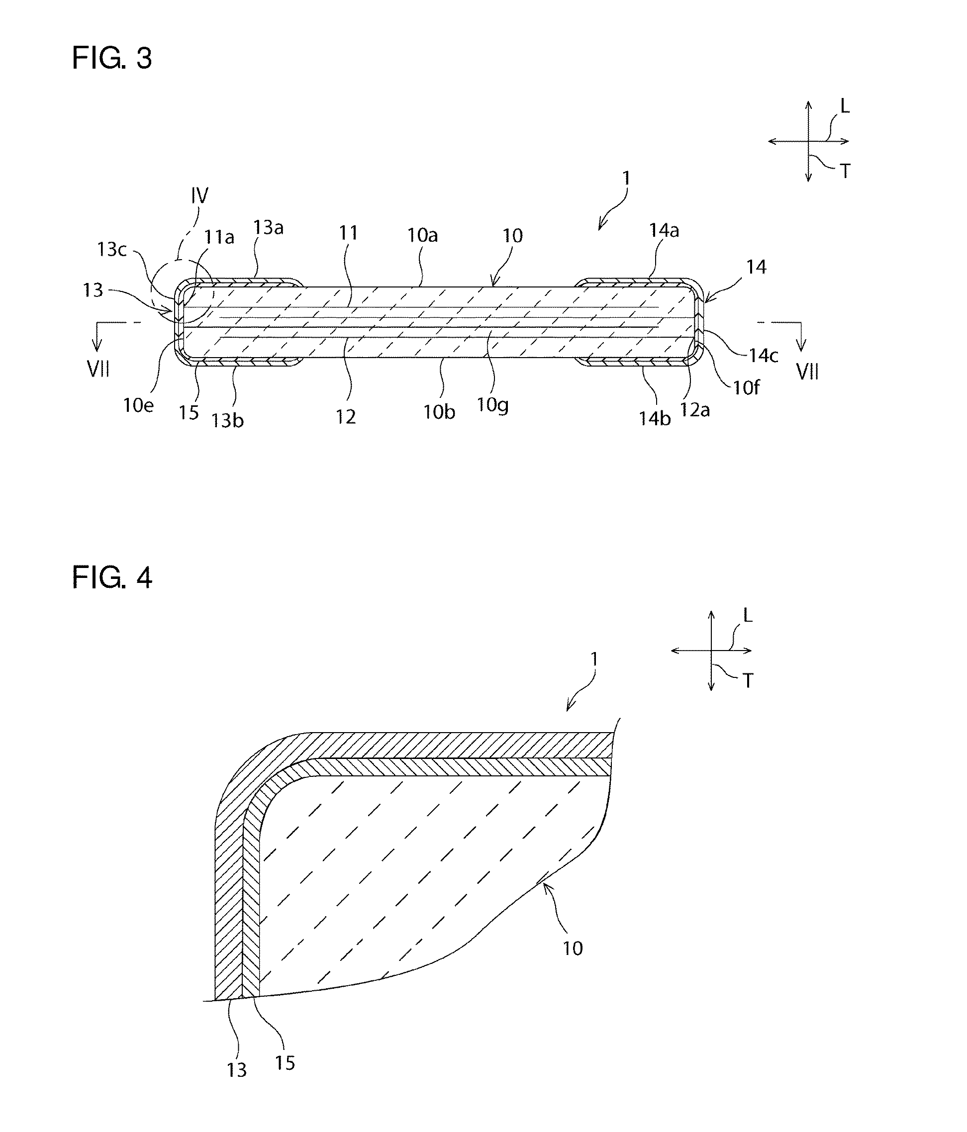
[0046]FIG. 1 is a schematic perspective view of a ceramic electronic component according to the first preferred embodime...

second preferred embodiment

[0094]FIG. 14 is a schematic perspective view of a ceramic electronic component according to a second preferred embodiment of the present invention.

[0095]In the above first preferred embodiment, an example has been described in which the first and second electrode terminals 13 and 14 and the coating layers 15 are located on the first and second side surfaces 10c and 10d. However, as shown in FIG. 14, the first and second electrode terminals 13 and 14 and the coating layers 15 may not be substantially located on the first and second side surfaces 10c and 10d.

[0096]The ceramic electronic component according to the second preferred embodiment can be produced, for example, in the following manner. A mother laminate 22 (see FIG. 15) is obtained in the same manner as in the method for producing the ceramic electronic component 1 according to the first preferred embodiment. In this preferred embodiment, next, as shown in FIG. 15, an electrically conductive pattern 23 having a configuratio...

third preferred embodiment

[0099]FIG. 16 is a schematic cross-sectional view of a ceramic electronic component according to a third preferred embodiment of the present invention.

[0100]In the above first preferred embodiment, an example has been described in which the first and second electrode terminals 13 and 14 and the coating layers 15 are located on both the first and second principal surfaces 10a and 10b. However, the present invention is not limited to this configuration. The first and second electrode terminals 13 and 14 and the coating layers 15 only have to be located somewhere on the surface of the ceramic body 10.

[0101]For example, as shown in FIG. 16, the first and second electrode terminals 13 and 14 and the coating layers 15 may be located on the second principal surface 10b but not located on the first principal surface 10a.


PUM


Abstract

A ceramic electronic component includes a ceramic body; a plurality of internal electrodes provided in the ceramic body and including ends exposed on a surface of the ceramic body; a coating layer covering a surface portion of the ceramic body on which the internal electrodes are exposed, the coating layer being made of a glass or resin medium in which metal powder particles are dispersed; and an electrode terminal provided directly on the coating layer and including a plating film. The metal powder particles define conduction paths electrically connecting the internal electrodes with the electrode terminal and have an elongated shape in cross section along a thickness direction of the coating layer. The metal powder particles defining the conduction paths have a maximum diameter not smaller than the thickness of the coating layer.

Description

BACKGROUND OF THE INVENTION[0001]1. Field of the Invention[0002]The present invention relates to ceramic electronic components.[0003]2. Description of the Related Art[0004]Ceramic electronic components, typified by ceramic capacitors, are widely used in electronic devices, such as a cellular phone or a portable audio player. A ceramic electronic component generally includes a ceramic body; internal electrodes whose ends are exposed on the surface of the ceramic body; and external electrodes disposed to cover the surface regions of the ceramic body on which the internal electrodes are exposed. Examples of the external electrode include one obtained by applying and baking an electrically conductive paste to the ceramic body to form a sintered metal film and then plating the sintered metal film, as described in JP-A-2002-203737, and one formed only of a plating film, as described in JP-A-2004-327983.[0005]However, because the electrically conductive paste used in forming the sintered m...

Claims


Application Information

Patent Timeline
IPC IPC(8): H05K7/00H01F17/00H01C7/00H01G4/005H02N2/00
CPCH01F27/292H01L41/0472H01G4/30H01C1/148H01C7/18H01F17/0006H05K7/00H01G4/005H02N2/00H01C7/008H01G4/2325H10N30/872B07C5/361B07C5/18B07C2501/009
Inventor NISHISAKA, YASUHIROSANADA, YUKIOKISUMI, TETSUYANAGAMOTO, TOSHIKI
Owner MURATA MFG CO LTD
Learn More