Wideband transmitter/receiver arrangement for multifunctional radar and communication

a multi-functional, transmitter-receiver technology, applied in the field of wideband multi-functional transmitter-receiver arrangement, can solve the problems of lack of multi-functional capability, poor signal cohabitation between the environmental signals, and limited function of fmcw radar

Active Publication Date: 2013-08-08
SAAB AB
View PDF33 Cites 38 Cited by
  • Summary
  • Abstract
  • Description
  • Claims
  • Application Information

AI Technical Summary

Benefits of technology

[0022]Cohabitation issues tend to become important for all radar frequencies as competing uses of the spectrum spreads upwards in frequency to established microwave radar bands. However the issue of cohabitation is particularly crucial for frequencies below about 1 GHz. A large fraction of all communication services are situated in this band. SAR operating below 1 GHz and with bandwidths of the order 100 MHz has the ability of penetrating ground and vegetation, and thus detect objects and structures hidden from ordinary sensors. There is an evident clash in that communication and this type of radar share the same frequencies. One application of the present invention is to moderate this clash.
[0023]Consider cohabitation interference mitigation of type 1. This could potentially be reduced if the radar is given an ability to receive and immediately repeat incident signals. This will have a similar effect in a communication channel as multipath effects to which communication modulation schemes must be significantly robust. Modern digital modulation techniques such as OFDM are particularly robust.

Problems solved by technology

The FMCW radar is however limited to said radar function and lacks any multifunctional capability.
Moreover, the FMCW radar exhibits poor signal cohabitation between its radar function and environmental signals.
Cohabitation issues tend to become important for all radar frequencies as competing uses of the spectrum spreads upwards in frequency to established microwave radar bands.
There is an evident clash in that communication and this type of radar share the same frequencies.
For wide band inference, e.g. digitally modulated television broadcast, this method results in a seriously large degradation of radar data and SAR image quality.
The larger the bandwidth of the radar, the larger the receive channel noise level.
On the other hand the possible isolation diminishes with increased bandwidth, due to e.g. the reduced dynamic range of analogue to digital converters ADCs and digital to analogue converters DACs operating at high sampling rates.
Hence the degree of isolation achievable in the digital suppression stages will be limited for such a system.
Another limiting factor is the accuracy of the required DACs.

Method used


Image

  • Wideband transmitter/receiver arrangement for multifunctional radar and communication
  • Wideband transmitter/receiver arrangement for multifunctional radar and communication
  • Wideband transmitter/receiver arrangement for multifunctional radar and communication

Examples


Embodiment Construction

[0054]In the following only one embodiment of the invention is shown and described, simply by way of illustration of one mode of carrying out the invention.

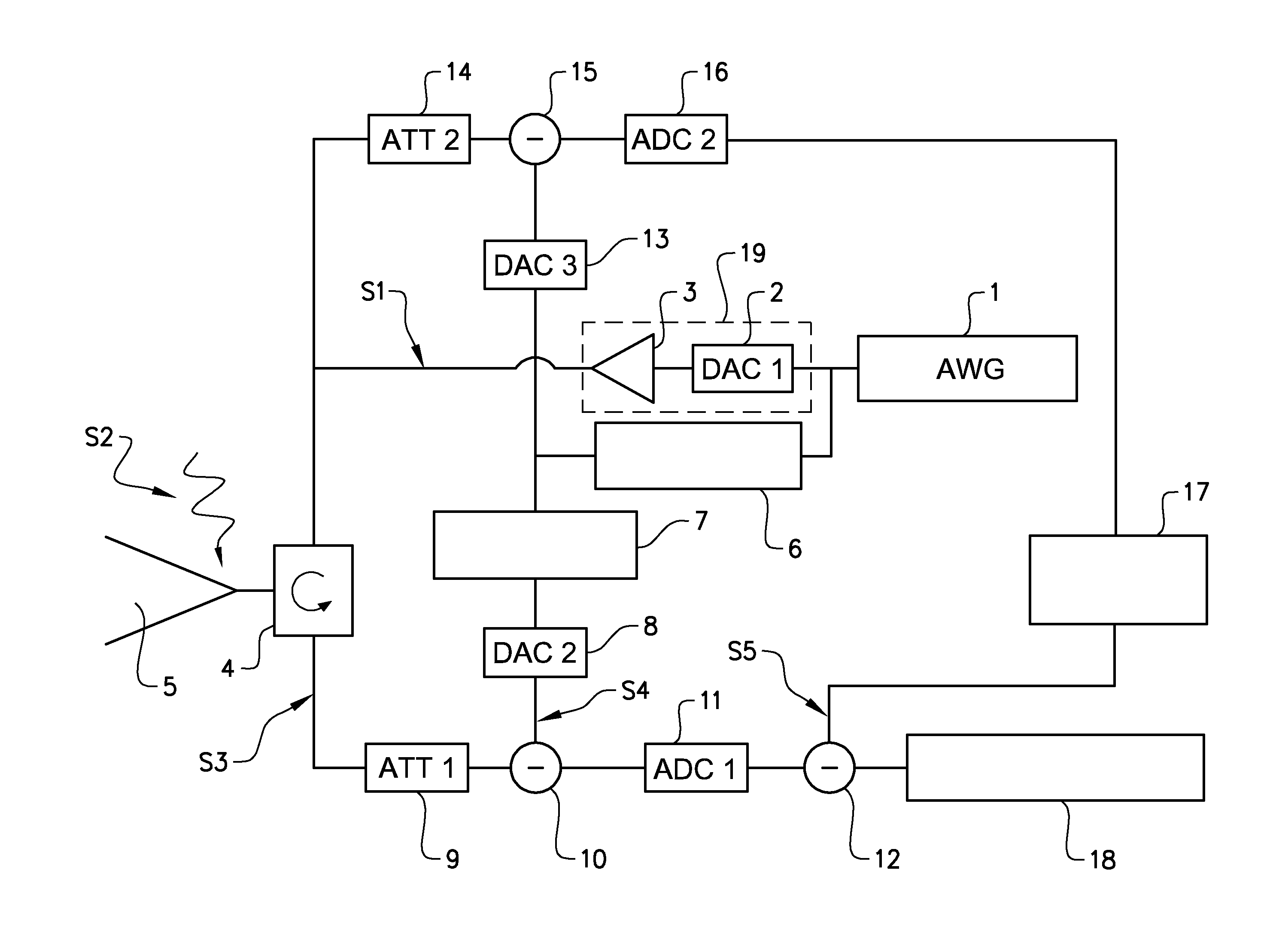
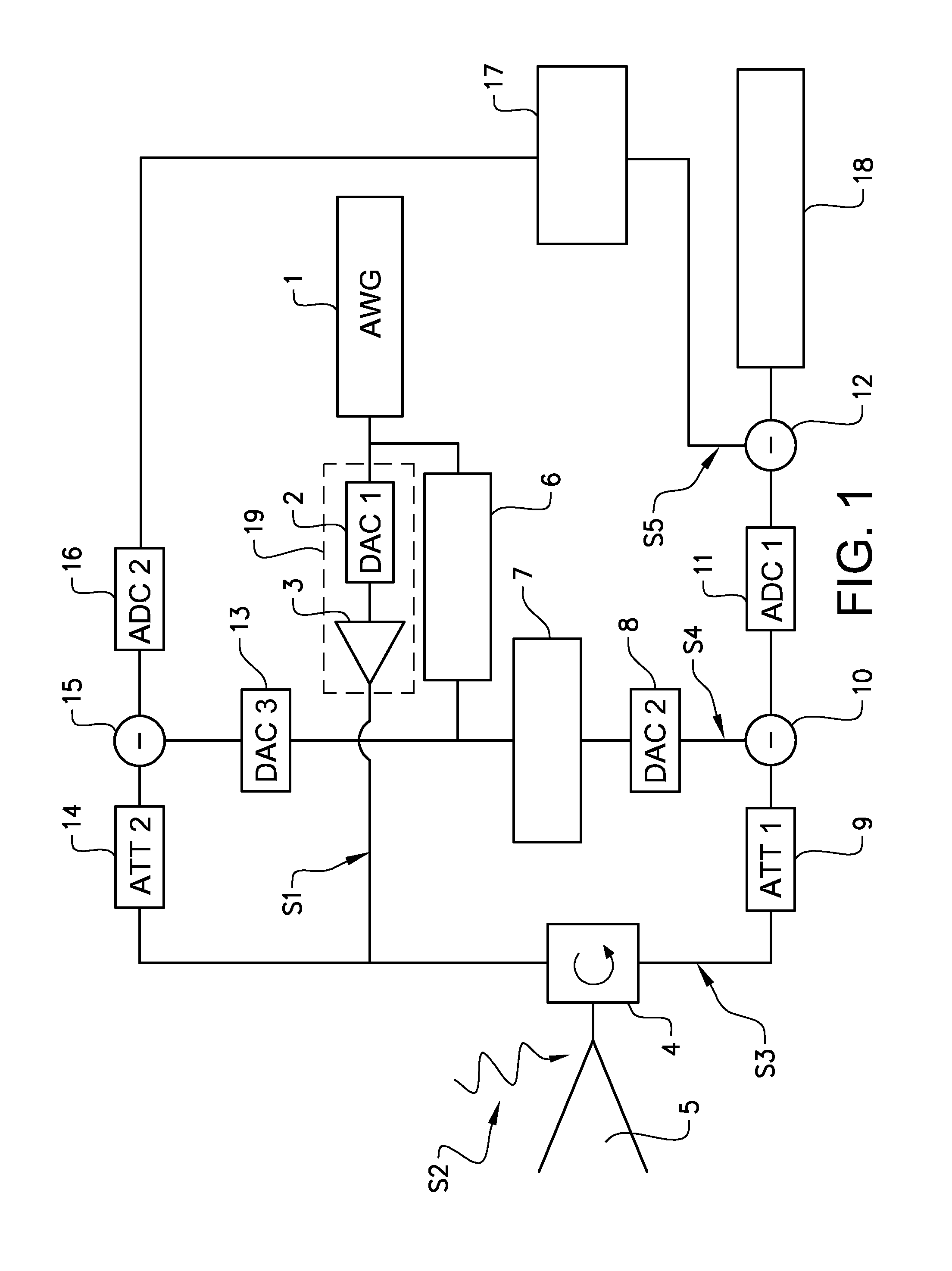
[0055]FIG. 1 shows the system building blocks of AWCW radar according to the invention. A digital arbitrary waveform generator AWG 1 feeds a transmitter 19 comprising a first digital to analogue converter DAC 2, and a power amplifier 3. The signal generated by the AWG 1 is thus converted to an analogue signal, which is amplified in the power amplifier 3. The transmitter 19 subsequently feeds a transmitter signal S1 into a RF isolator 4, which serves to control the direction of signal flow. The isolator 4 is further connected to an antenna arrangement 5, and to a receiver, such that signals S1 from the transmitter 19 are routed by means of the isolator 4 to the antenna arrangement 5 and isolated from the receiver, and incident signals S2 on the antenna are routed solely to the receiver. The term isolator (4) is here considered to ...


PUM


Abstract

A transmitter/receiver arrangement comprises a digital arbitrary waveform generator AWG connected to a transmitter. Said waveform generator is configured to generate an arbitrary waveform within a given bandwidth. Said transmitter/receiver arrangement further comprises an antenna arrangement configured to emit a transmitter signal, and to receive an incident signal, a receiver configured to receive a receiver signal, and an analogue isolator connected to said antenna arrangement, said transmitter, and said receiver. Said analogue isolator is adapted to route said transmitter signal from said transmitter to said antenna arrangement, and said incident signal from said antenna arrangement to said receiver, and to isolate said transmitter signal from said receiver signal. Said receiver is adapted to cancel any residual transmitter signal in said receiver signal by means of at least one digital model of at least said isolator, said antenna arrangement, and said transmitter.

Description

TECHNICAL FIELD[0001]The present invention relates to a wideband multifunctional transmitter and receiver arrangement, preferably for transmitting and receiving at VHF, UHF or in the microwave bands. Such an arrangement can simultaneously and in the same frequency band serve as radar, surveillance, and communication system.BACKGROUND ART[0002]In its simplest form, prior art continuous wave CW radar emits a single frequency continuous wave. By measuring the Doppler shift of the return signal, the CW radar can determine the velocity of detected objects. By linear frequency modulation (sawtooth) of the continuous wave in a CW radar, a frequency-modulated continuous wave FMCW radar system is provided. The frequency modulation of the CW has the advantage that also the distance to a detected object can be determined. Such a FMCW radar system is known from U.S. Pat. No. 3,789,398. The FMCW radar is mainly motivated by the fact that it minimizes the peak-to-average power ratio for the radar...

Claims


Application Information

Patent Timeline
Patent Type & Authority Applications(United States)
IPC IPC(8): H04B1/44G01S7/03
CPCG01S7/006G01S7/038G01S7/4021H04B1/44G01S13/90G01S7/03G01S13/32G01S2013/0272
Inventor HELLSTEN, HANS
Owner SAAB AB
Why Eureka
Try Eureka