Isolated dynamic current converters

Active Publication Date: 2013-08-08
SENTIENT ENERGY TECH LLC
View PDF2 Cites 56 Cited by
  • Summary
  • Abstract
  • Description
  • Claims
  • Application Information

AI Technical Summary

Benefits of technology

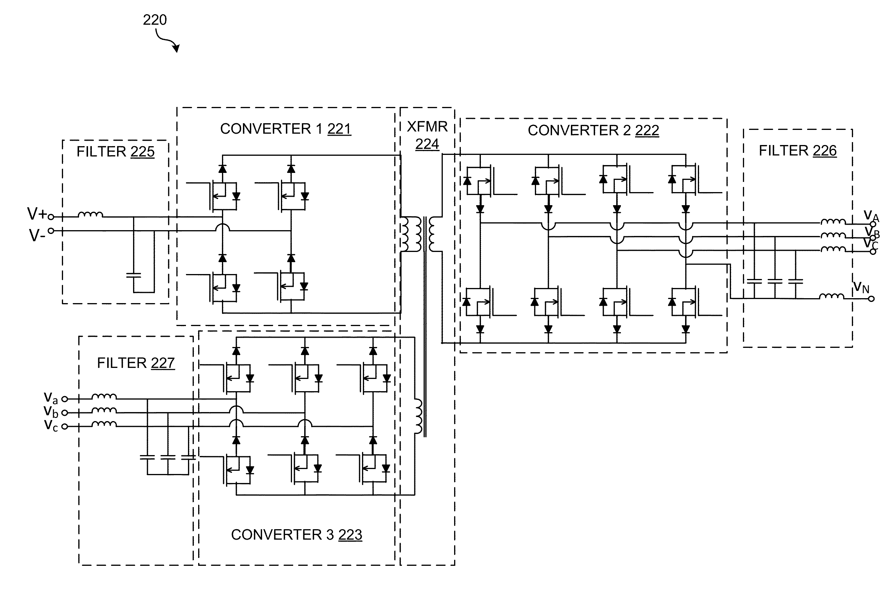
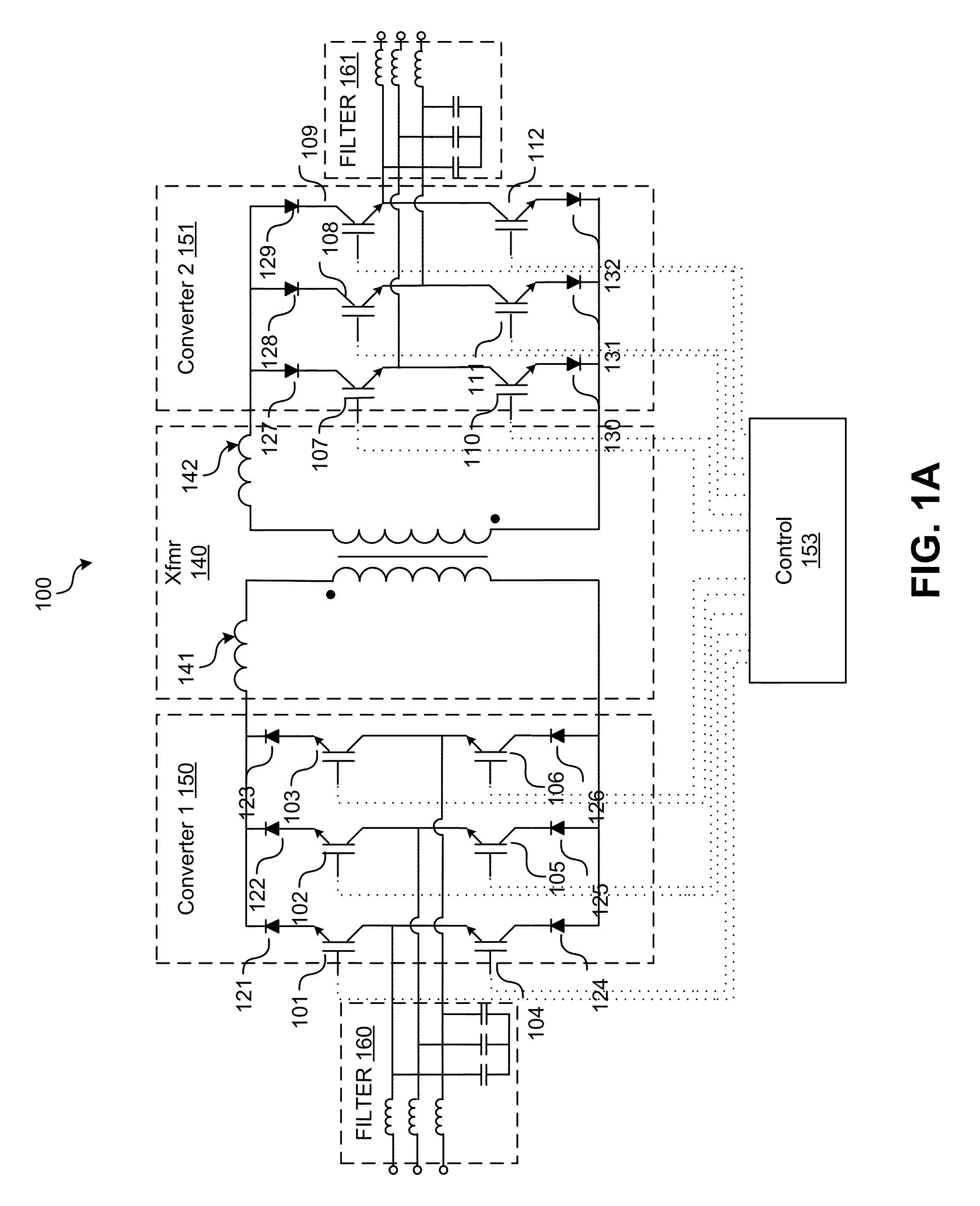
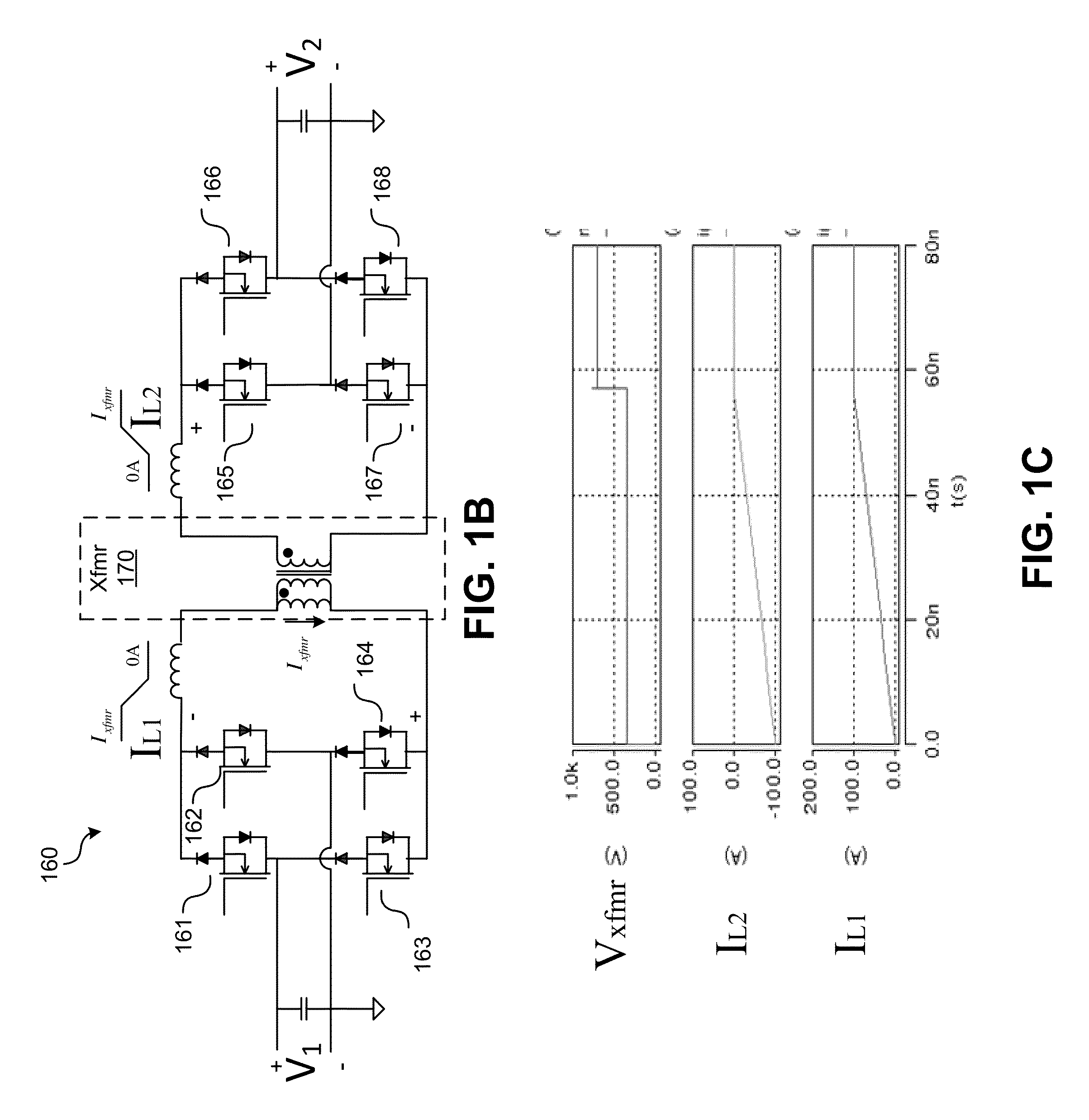
[0008]Isolated Dynamic-Current (“Dyna-C”) converters are converters that convert incoming 3-phase AC or DC power to a mix of DC and AC power via an isolation link. In various embodiments, the isolation is a high-frequency transformer. Various embodiments provide bi-directional converters that are current source based with dynamic current response capability. Various embodiments may provide AC/AC, DC/DC, AC/DC, or DC/AC power conversions. Some embodiments that convert AC power to DC power may comprise two-q

Problems solved by technology

When galvanic isolation is required, multi-stage conversion is necessary for converting AC power to AC power or AC power to DC power, which increases losses and complexity significantly.
Large DC capacitors are required to minimize stage-to-stage dynamic interaction and to improve stability, which makes these topologies expensive and have limited life.
Moreover, efficiencies of voltage source based converters are low due to fixed DC voltages, and the need for multiple conversion stages when galvanic isolation is desired.
Under fault conditions, voltage source based converters require very fast protection, but high fault currents are still challenging to the protection system.
Additionally, voltage source based converters require large inductive filters on the AC line side, which further adds costs and size, and increases control complexity.
With every stage included in the power conversion chain, system efficiency deteriorates while complexity, volume, and cost increase.
As an alternative, a two-stage AC-AC DAB converters have been proposed, but are seen to have a limited operating range due to the use of single-phase sinusoidal sources and the subsequ

Method used


Image

  • Isolated dynamic current converters
  • Isolated dynamic current converters
  • Isolated dynamic current converters

Examples


Example

[0046]The figures are not intended to be exhaustive or to limit the invention to the precise form disclosed. It should be understood that the invention can be practiced with modification and alteration, and that the invention be limited only by the claims and the equivalents thereof.

DETAILED DESCRIPTION OF THE EMBODIMENTS OF THE INVENTION

[0047]Conventional converters with high-frequency isolation usually comprise an AC / DC conversion stage, followed by a DC / DC with high-frequency isolation, which is followed by a DC / AC conversion stage. Solid state transformers with such configuration have high switch counts with additional controllers, gate drives, sensors and heatsinks. These solid state transformers are expensive, large, complex, and have poor efficiency due to multiple devices in the current conduction path.

[0048]Isolated dynamic current (“Dyna-C”) converters are provided. One embodiment comprises a first single-stage converter, a high-frequency transformer, and a second single-s...


PUM


Abstract

Isolated Dynamic-Current (“Dyna-C”) converters are converters that convert incoming 3-phase AC or DC power to a mix of DC and AC power via an isolation link. In various embodiments, the isolation link is a high-frequency isolation transformer. Isolated Dyna-C converters may provide a high-frequency galvanic isolation and are able to convert three-phase AC power to three-phase AC power, or three-phase AC power to DC and vice versa. The topology is minimal and the costs are low. Isolated Dyna-C converters provide fast current responses and keep the losses low by using a simplified two-stage conversion and providing a magnetizing current that is dynamically controllable and tailored to the load. An isolated Dyna-C converter may synthesize currents at its input or output ports with an arbitrary phase that is relative to the grid or load voltages, thereby enabling a full independent control over the active and reactive power at its ports.

Description

CROSS-REFERENCE TO RELATED APPLICATIONS[0001]This application claims benefit of U.S. Provisional Patent Application No. 61 / 579,610, filed on Dec. 22, 2011, entitled “Systems and Methods for Managing Power”, which is hereby incorporated herein by reference in its entirety.TECHNICAL FIELD[0002]The present invention(s) relate generally to galvanically isolated current based converters. More particularly, the invention(s) relate to systems and methods of bi-directional converters, implementation, and control thereof.DESCRIPTION OF THE RELATED ART[0003]With the advancement in technologies, solid-state converters are used in a wide range of applications, from small switching power supplies in personal electronics to large power systems that transmit electric power. These converters may convert alternating current (AC) power to direct current (DC) power, or vice versa. When galvanic isolation is required, multi-stage conversion is necessary for converting AC power to AC power or AC power t...

Claims


Application Information

Patent Timeline
IPC IPC(8): H02M1/00H02M1/12H02M7/42H02M7/02H02M5/00
CPCH02M1/00H02M7/02H02M5/00H02M7/42H02M7/493H02M3/33576H02M5/225H02M7/23H02M7/4807H02M1/126H02M1/0043
Inventor DIVAN, DEEPAKRAJ M.PRASAI, ANISHCHEN, HAO
Owner SENTIENT ENERGY TECH LLC
Why Eureka
Try Eureka