Idling control device for vehicle

a technology for controlling devices and vehicles, applied in the field of vehicles, can solve problems such as the control stability reduction of the idling revolution speed control, and achieve the effects of superior responsive characteristic and controllability, stable idling drive, and superior response characteristic and controllability

Active Publication Date: 2013-08-08
NISSAN MOTOR CO LTD
View PDF16 Cites 11 Cited by
  • Summary
  • Abstract
  • Description
  • Claims
  • Application Information

AI Technical Summary

Benefits of technology

[0006]In a case where the ignition timing during the idling drive in the engine cold state is retarded, as the retardation angle quantity (retardation quantity) of the ignition timing becomes larger, the exhaust rise temperature effect becomes higher. However, due to the reduction in a combustion stability and a variation in the engine revolution speed, a control stability of the idling revolution speed control is reduced.
[0007]Therefore, it is an object of the present invention to provide an idling revolution speed control apparatus for a vehicle in which the engine and the motor are mutually linked together and which expands a retardation angle quantity of the firing timing of the engine while a stability of the idling revolution speed control is maintained to promote a warm-up of the engine.
[0009]In order to make a best use of the characteristics of the vehicle in which the engine and the motor are equipped, during the idling drive in which the engine speed is maintained at a predetermined target idling revolution speed, an engine idling mode in which the idling revolution speed control is carried out according to the opening angle of an engine throttle valve and a motor idling speed control mode in which the idling revolution speed control is carried out through the revolution speed control of the motor are switchable in accordance with the vehicle driving state. Thus, if, basically, the motor idling mode is used by means of the motor having superior responsive characteristic and controllability, a stable idling drive can be achieved. In addition, in a case where it becomes difficult to maintain the idling drive in the motor idling mode due to the insufficient charge quantity of the battery, the target idling revolution speed can be maintained using the engine idling mode.
[0010]Then, according to the present invention, during the idling drive in the engine cold state in which the firing timing of the engine in the motor idling mode is more largely retarded than the ignition timing of the engine in the engine idling mode. In other words, in the motor idling mode, the retardation quantity of the firing timing is expanded to be larger than the engine idling mode in which the idling revolution speed control is performed by the revolution speed control of the motor is switchable according to the vehicle driving state. Thus, during, for example, the idling drive, a stable idling drive can be performed using the motor idling mode by means of the motor which is superior in a response characteristic and a controllability. In addition, in a case where a charge quantity of the battery is insufficient or in a case where the idling drive in the motor idling mode is difficult, the target idling revolution speed can be maintained using the motor idling mode.
[0011]According to the present invention, a retardation angle quantity of the firing timing of the engine is expanded without impairing an idling stability so that the warm-up of the engine can be promoted during the idling drive in the engine cold state.

Problems solved by technology

However, due to the reduction in a combustion stability and a variation in the engine revolution speed, a control stability of the idling revolution speed control is reduced.
In addition, in a case where it becomes difficult to maintain the idling drive in the motor idling mode due to the insufficient charge quantity of the battery, the target idling revolution speed can be maintained using the engine idling mode.

Method used


Image

  • Idling control device for vehicle
  • Idling control device for vehicle
  • Idling control device for vehicle

Examples


Embodiment Construction

[0019]Hereinafter, a detailed description of a preferred embodiment according to the present invention will be made on a basis of drawings.

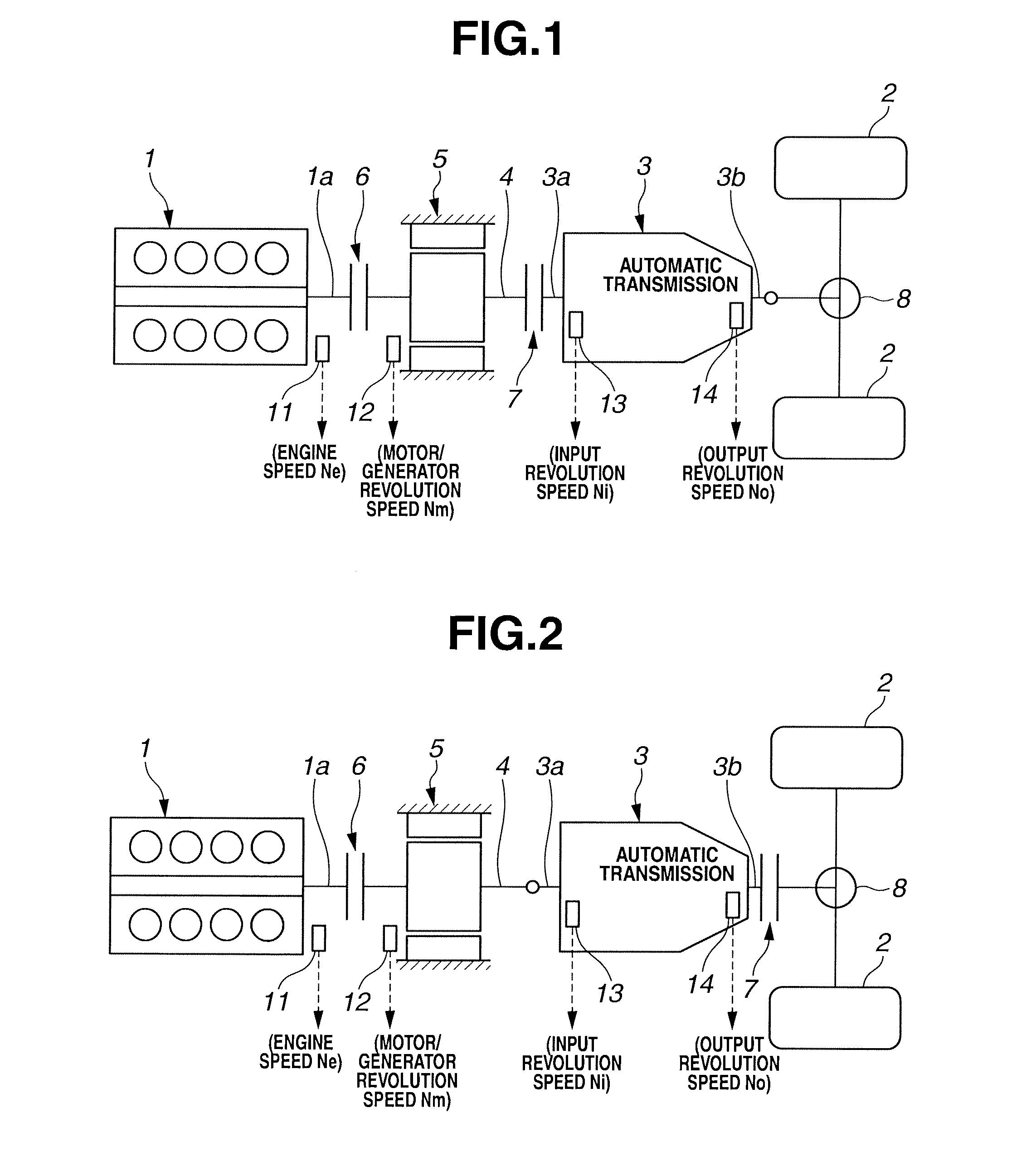
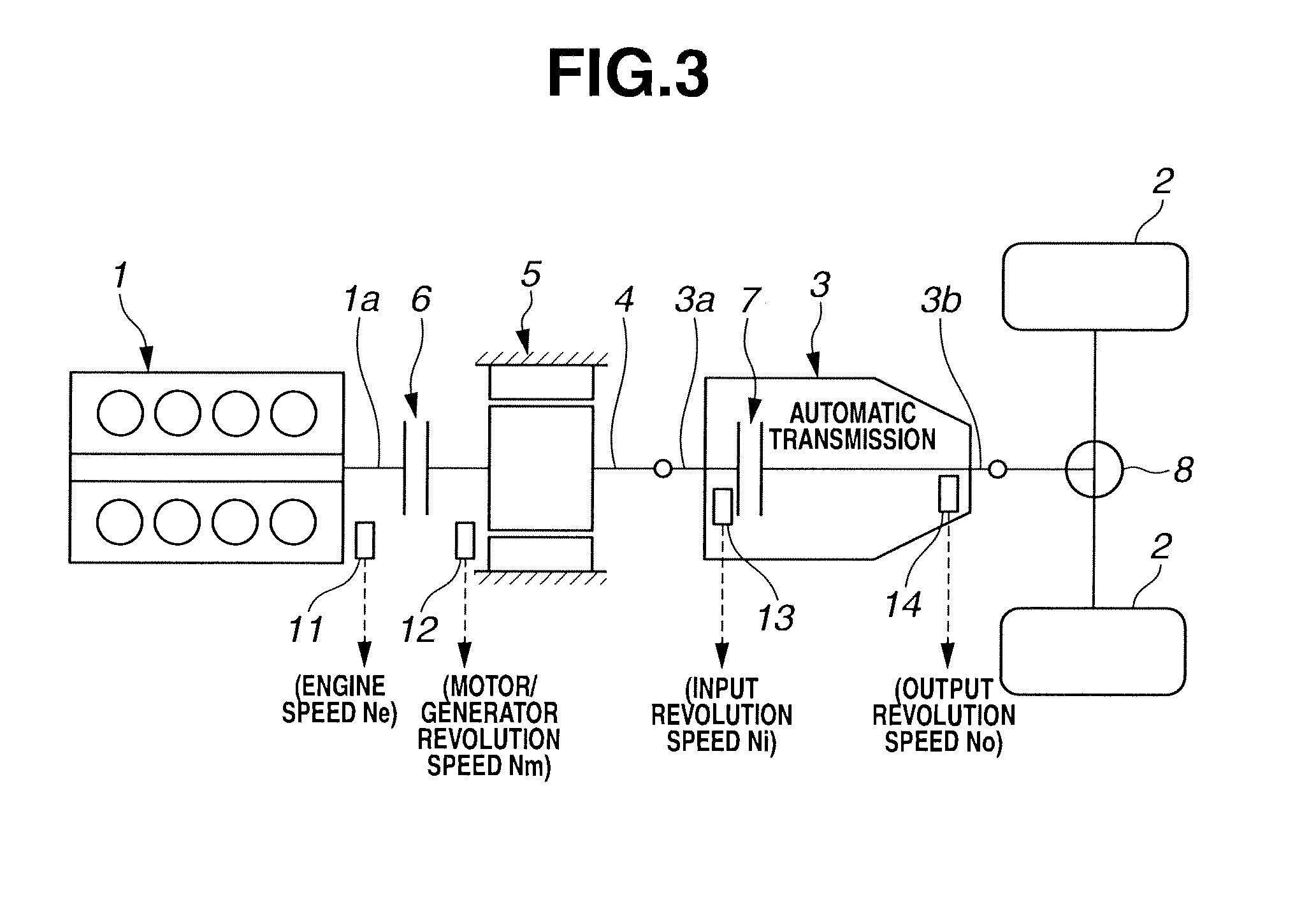
[0020]First, a basic structure of a hybrid vehicle to

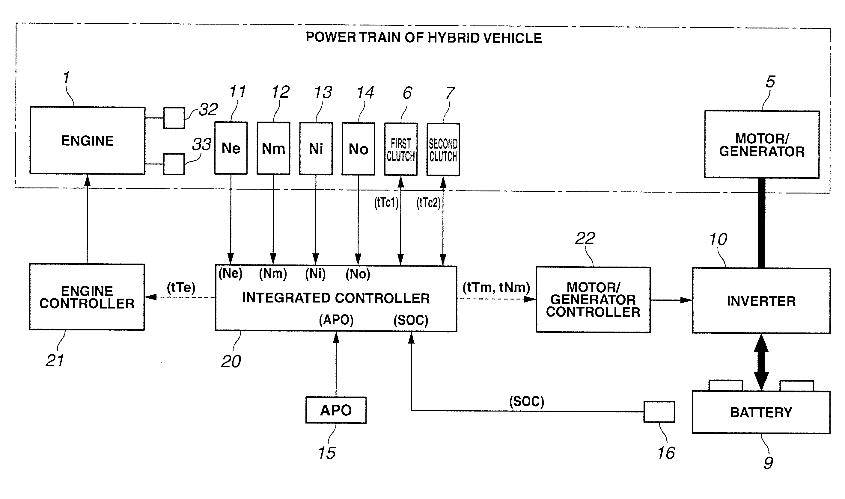
[0021]In the power train of the hybrid vehicle shown in FIG. 1, an automatic transmission 3 is arranged in a tandem configuration at a rear position of a vehicle longitudinal direction of engine 1 in the same way as a normal rear wheel driving vehicle. A motor / generator 5 is integrally mounted on a shaft 4 via which a revolution from engine 1 (crankshaft la) is transmitted to an input shaft 3a of automatic transmission 3.

[0022]Motor / generator 5 is constituted by a synchronous type motor using permanent magnets as a rotor, acting as a motor (so-called, a power running) and acting as a generator (a power generator) (so-called, a regeneration). As described above, motor / generator 5 is interposed between engine 1 and automatic transmission 3. A first clutch 6 is interposed between engine 1 and auto...


PUM


Abstract

An idling revolution speed control which maintains an engine speed at a predetermined target idling revolution speed during the idling drive includes an engine idling mode which performs the idling revolution speed control through an engine and a motor idling mode which performs the idling revolution speed control through a motor. The two modes are switched in accordance with a battery charged state. During the to idling drive in an engine cold state, an ignition timing of the engine in the motor idling mode is retarded and the retardation quantities R3, R4 are expanded to be larger than the retardation quantities R1, R2 in the engine idling mode. Thus, a rise in an exhaust temperature of the engine is promoted.

Description

TECHNICAL FIELD[0001]The present invention relates to a vehicle such as a hybrid vehicle in which both of an engine and a motor mutually linked with each other are used together as power sources of the vehicle and, more specifically, relates to a control at a time of an idling drive in an engine cold state.BACKGROUND ART[0002]Patent document 1 describes a technique which, in a hybrid vehicle in which an engine and a motor are equipped as power sources of the vehicle, improves a control stability of the idling revolution speed control by enabling a switching between an engine idling mode in which an idling speed revolution speed control is carried out through the engine and a motor idling mode in which the idling revolution speed control is carried out through the motor in accordance with a charged state (SOC) of the battery, during an idling drive.[0003]Incidentally, during the idling drive in the cold state in which a warm-up of the engine is not completed, an exhaust rise temperat...

Claims


Application Information

Patent Timeline
Patent Type & Authority Applications(United States)
IPC IPC(8): B60W20/00B60W10/08B60W10/06
CPCB60W10/06Y02T10/6221B60W20/00B60W2510/0676B60W2510/244B60W2710/0644B60W2710/065B60W2710/0688B60W2710/0694B60Y2200/92F02D31/001F02D41/0245F02D41/083F02D2200/503F02N2200/061F02P5/1508Y02T10/46Y02T10/6286B60W2600/00Y10S903/93B60K6/48B60W10/08Y02T10/40Y02T10/62B60W2556/00
Inventor WATANABE, KEIOHNO, TAKESHI
Owner NISSAN MOTOR CO LTD
Why Eureka
Try Eureka