Minimal Quantity Lubricating System

a lubricating system and small quantity technology, applied in the field of small quantity lubricating system, can solve the problems of high stress on the tool, heating or destruction of the tool, etc., and achieve the effect of reducing the overall size of the excitation component, high oscillation amplitude, and efficient droplet generation

Inactive Publication Date: 2013-08-15
ROBERT BOSCH GMBH
View PDF9 Cites 21 Cited by
  • Summary
  • Abstract
  • Description
  • Claims
  • Application Information

AI Technical Summary

Benefits of technology

[0008]In accordance with an advantageous development of the invention the excitable material of at least one oscillating unit can be piezoelectric or magnetostrictive, wherein the at least one oscillating unit can preferably reach an oscillation amplitude in the range of 2 μm to 200 μm at its free end. The excitable material of at least one oscillating unit may thus be a piezoelectric material, in particular a piezoceramic, such that the piezoelectric material deforms upon application of an electric voltage. Alternatively or also in addition, one or more oscillating units can also be driven by means of a magnetostrictive material. These deform their volume as a result of an applied magnetic field. The driving magnetic field can be output to the magnetostrictive material by means of a magnet coil through which current is made to flow and by means of an iron core. The excitation actuator can thus be formed as a piezoelectric Langevin oscillator or as a magnetostriction oscillator. In particular, it is furthermore advantageous here if the at least one oscillating unit can reach an oscillation amplitude in the range of 2 μm to 200 μm at its free end. A correspondingly high oscillation amplitude is advantageous for efficient droplet generation in the fluid flow and therefore for a fine mist of the fluid.
[0009]In accordance with a further advantageous embodiment, the operating frequency of the at least one oscillating unit may lie in the range between 10 kHz and 1000 kHz, preferably between 15 kHz and 60 kHz, more preferably above 20 kHz, in particular between 35 kHz and 45 kHz, and approximately at 40 kHz. Due to an excitation frequency in the ultrasound range, the overall size of the excitation components reduces with increasing frequency, but with increasing mechanical load of the oscillation system, wherein advantageous size ratios with high performance are provided in the selected frequency range alongside advantageous weight of the minimal quantity lubricating system, which facilitates use in the form of a hand-held minimal quantity lubricating system and in the case of integration in a hand-held tool.
[0010]A quantity of cooling lubricating fluid to be dispensed can advantageously be set by the electronic unit by means of a timed cycle control. It is thus conceivable for the electronic unit to excite the oscillating unit intermittently, in particular at intervals of 10-5000 ms, preferably 50 to 1200 ms, to regulate a volume of dispensed fluid. Simple timed cycle control of the quantity of fluid dispensed can dispense with mechanical metering means, wherein a highly precise and efficient dispensing of fluid can be enabled by electronic actuation and regulation of the oscillating unit.
[0011]In accordance with an advantageous development, an airflow generated by a fan and that can be guided in the nozzle may be used to determine direction and / or to expand the fluid mist. The airflow assists the atomization of the fluid mist and steers it toward the machining site to be cooled and / or to be lubricated, so that low fluid use, high cooling and lubricating effect, and low soiling of external tool and workpiece regions are enabled.
[0012]In accordance with a further advantageous development, the nozzle and / or the fluid duct and / or the fluid feed line may comprise at least one cross-sectional tapering to influence a volume of dispensed fluid and preferably to achieve a capillary effect, and / or the fluid duct may extend through the oscillating unit in a manner in which it is angled or bent once or more than once. A cross-sectional tapering regulates the volume flow rate and, as a result of the capillary forces produced by the reduced cross section, can prevent a backflow and also independent discharge of the fluid. It is conceivable to design the cross-sectional tapering so as to be adjustable, in particular electrically or mechanically regulatable, for example by means of an electrically or mechanically acting throttle, valve or the like, so as to make a volume flow rate regulation and / or a capillary effect actively adjustable. An embodiment of the fluid duct in which it is angled or bent once or more than once can ensure an improved transfer of pulse from the oscillating unit to the fluid to be atomized and can also enable a greater flowthrough volume.
[0013]In accordance with a further advantageous development, the fluid feed line can be coupled to the oscillating unit in the axial direction of oscillation, or the fluid feed line can be coupled to the oscillating unit substantially at right angles to the axial direction of oscillation in the region of an oscillation node. Axial coupling of the fluid feed line in the axial direction of oscillation makes it possible to easily couple the fluid into the pulsing region of the oscillating unit, in which the fluid duct is subjected to just low mechanical stresses. Furthermore, a lateral, substantially right-angled coupling-in at an oscillation node point is conceivable, at which a possible bearing point of the oscillating unit is arranged, wherein the fluid duct is subject to hardly any mechanical stress.

Problems solved by technology

Within the scope of material machining processes, in particular in material removal machining, the tool, for example a drill bit, a cutting blade, an engraving needle, a chisel tip, etc., is often subject to high stress.
This stress can lead to heating or destruction of the tool.

Method used


Image

  • Minimal Quantity Lubricating System
  • Minimal Quantity Lubricating System
  • Minimal Quantity Lubricating System

Examples


Embodiment Construction

[0030]Like or similar components are denoted by like reference signs in the figures.

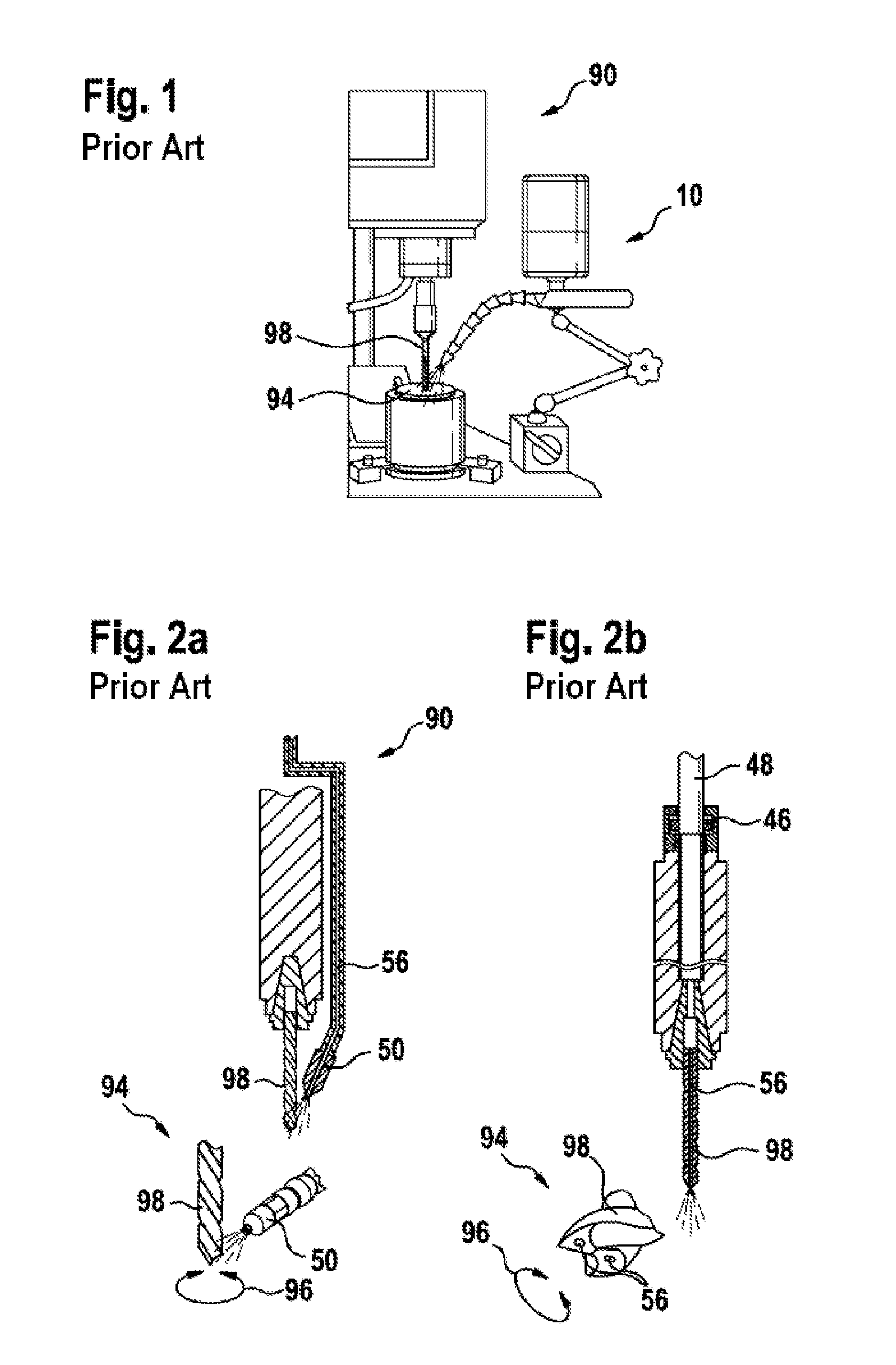
[0031]FIGS. 1 and 2 illustrate minimal quantity lubricating systems known from the prior art for cooling and / or lubricating a drilling tool 98 of a bench drill 90. A self-sufficient minimal quantity lubricating system 10 is illustrated in FIG. 1 and dispenses a cooling fluid at the drilling site of the working region 94 of a bench drill 90. The lubricating system 10 can be provided in a versatile manner on different machine tools 90 to cool and / or lubricate. Atomization occurs by means of compressed air, which is generated by an external compressor and is coupled into the atomizer nozzle. FIGS. 2a and 2b show basic illustrations of outer and inner minimal quantity lubrication respectively. Whereas the fluid is atomized in FIG. 2a at the working region 94 of the tool through an external nozzle 50, wherein the fluid 30 is supplied by means of a fluid duct 56, in FIG. 2b the lubricating fluid is supplie...


PUM


Abstract

A minimal quantity lubricating system for a handheld electric power tool is configured to output a lubricating fluid for cooling and/or lubricating a material machining process. The system comprises at least one oscillating unit, an electronic unit for applying at least control and/or feedback signals to the at least one oscillating unit, an operating power unit for providing electric power to the electronic unit, a storage tank for the lubricating fluid, and at least one nozzle associated with the at least one oscillating unit for feeding and atomizing the lubricating fluid in a tool working area. A fluid feed line connects the storage tank to a capillary feed of the lubricating fluid to the oscillating unit, and at least one fluid channel at least partially runs through the oscillating unit to connect the oscillating unit to the nozzle for pulsing the lubricating fluid.

Description

PRIOR ART[0001]The invention relates to a minimal quantity lubricating system for dispensing a fluid for cooling and / or lubricating a material machining process.[0002]Within the scope of material machining processes, in particular in material removal machining, the tool, for example a drill bit, a cutting blade, an engraving needle, a chisel tip, etc., is often subject to high stress. This stress can lead to heating or destruction of the tool. To increase the service life of the tool, cooling and lubricating additives, in particular cooling lubricating liquids, such as water / oil mixtures, are dispensed at a working region of the tool to cool and lubricate the tool, and result in a decrease in tool temperature and lubrication of the machining site. Such a cooling lubricating agent, which will also be referred to hereinafter as fluid or as lubricating fluid, may be a liquid for cooling material machining processes, such as water or alcohol, or a lubricant such as rapeseed oil. In addi...

Claims


Application Information

Patent Timeline
Patent Type & Authority Applications(United States)
IPC IPC(8): B27C3/00
CPCB05B17/063B27C3/00B23Q11/1046B23Q11/10Y02P70/10
Inventor ROSER, JOCHENDI NICOLANTONIO, ALDODELFINI, STEFANO
Owner ROBERT BOSCH GMBH
Why Eureka
Try Eureka