
Configurable Shield for Hand-Held Electronic Device

a technology for electronic devices and shields, applied in the direction of coupling device connections, flexible screening containers, and screening rigid plastic containers, etc., can solve the problems of both end user and network security, cell phone radiation is potentially carcinogenic, and distracted driving

Active Publication Date: 2013-08-15
DAVIS PAUL FITZGERALD
View PDF9 Cites 28 Cited by
  • Summary
  • Abstract
  • Description
  • Claims
  • Application Information

AI Technical Summary

Benefits of technology

The patent describes a device shield that protects sensitive electronic devices from security threats. The shield can be engaged or disengaged to prevent RF signals from leaving or entering the device, respectively. The housing can also have an additional closure element to further secure the device. The technical effect of the device shield is to provide a secure and reliable barrier for sensitive electronic devices, protecting them from malicious infections and unauthorized access.

Problems solved by technology

Recent scientific studies have concluded that radiation associated with cell phones is potentially carcinogenic.
Inherent with this technological boom in cell phones and related apps are the issues of both end user and network security.
Another issue is location privacy; even when a cell phone has its GPS feature disabled, that phone is still being tracked as it transmits from cell tower to cell tower in transit.
Separate from privacy and security considerations is the issue of distracted driving.
Equally on the rise are the numbers of fatal car accidents and injury accidents due to drivers being distracted by using a cell phone or texting.

Method used


Image

  • Configurable Shield for Hand-Held Electronic Device
  • Configurable Shield for Hand-Held Electronic Device
  • Configurable Shield for Hand-Held Electronic Device

Examples


Embodiment Construction

Overview: Single-Compartment Shield for Housing Portable Device (Schematic)

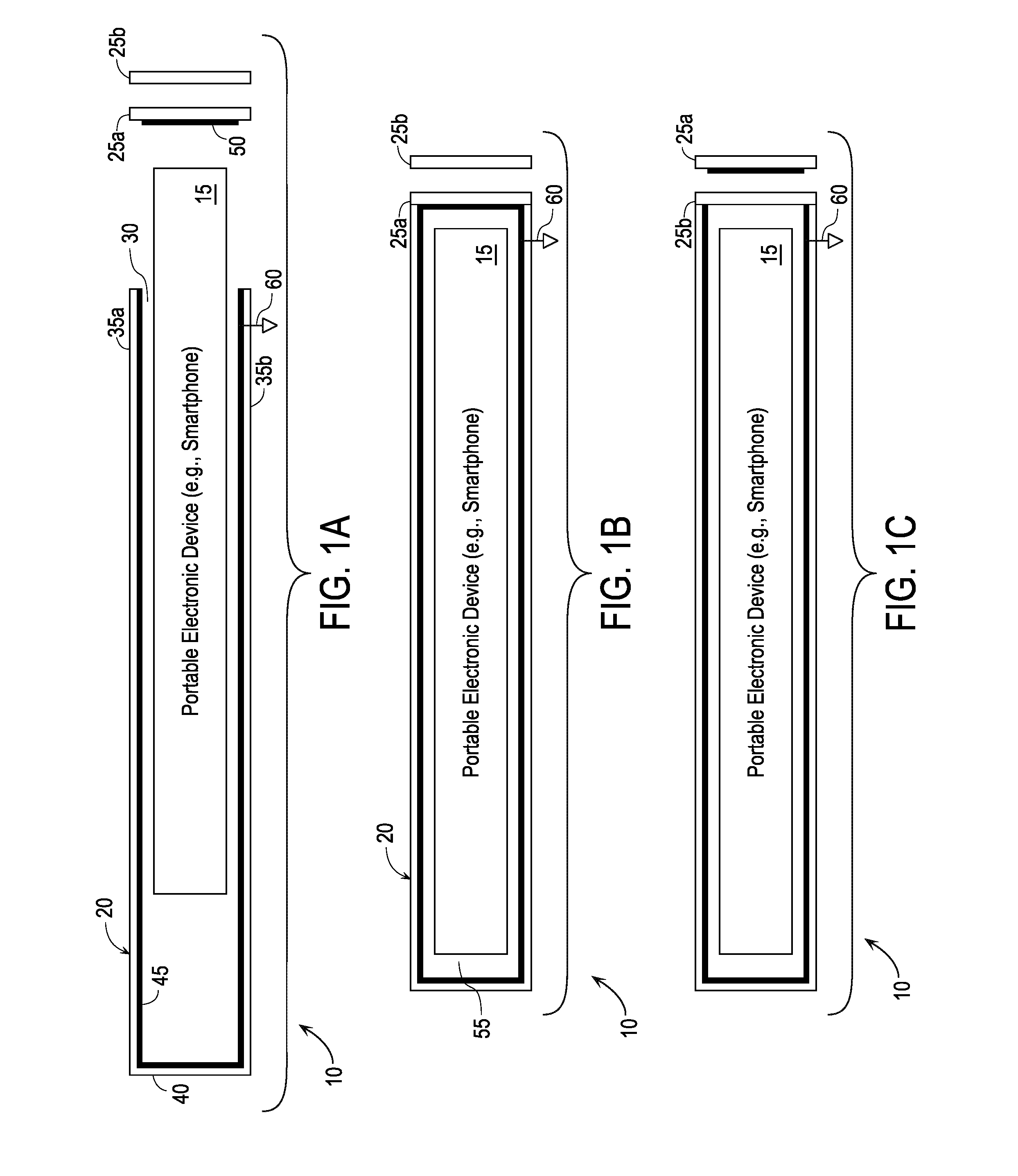
[0050]FIGS. 1A, 1B, and 1C are high-level schematic side sectional views showing configurations for a single-compartment shield 10 into which a portable electronic device 15 such as a smartphone can be inserted. In short, the shield is shown as including a first or main housing portion formed as an open-ended main container element 20 sized to accommodate a major portion or all of the portable device, and a second housing portion formed as one or more closure elements 25a and 25b. The first and second housing portions can be engaged to provide a single compartment (sometimes referred to as the “device compartment”) for holding the portable device and allowing RF signals to be selectively blocked.

[0051]FIG. 1A shows the portable device only partially inserted into container element 20 and the two closure elements 25a and 25b separated from the container element, i.e., disengaged from the container element. The...


PUM


Abstract

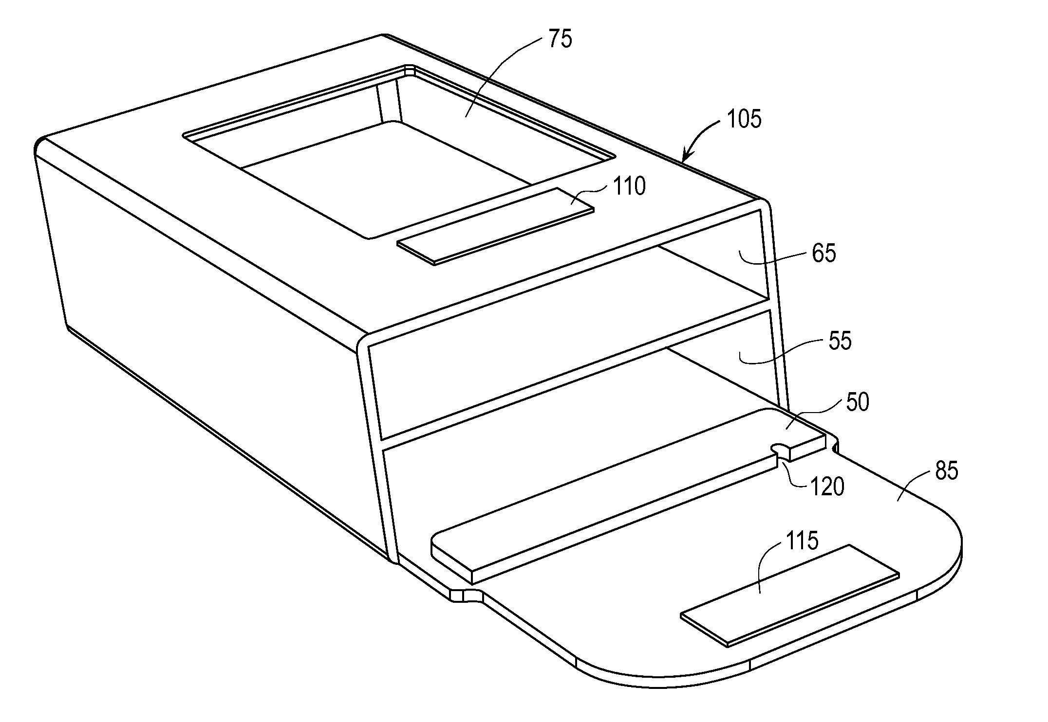
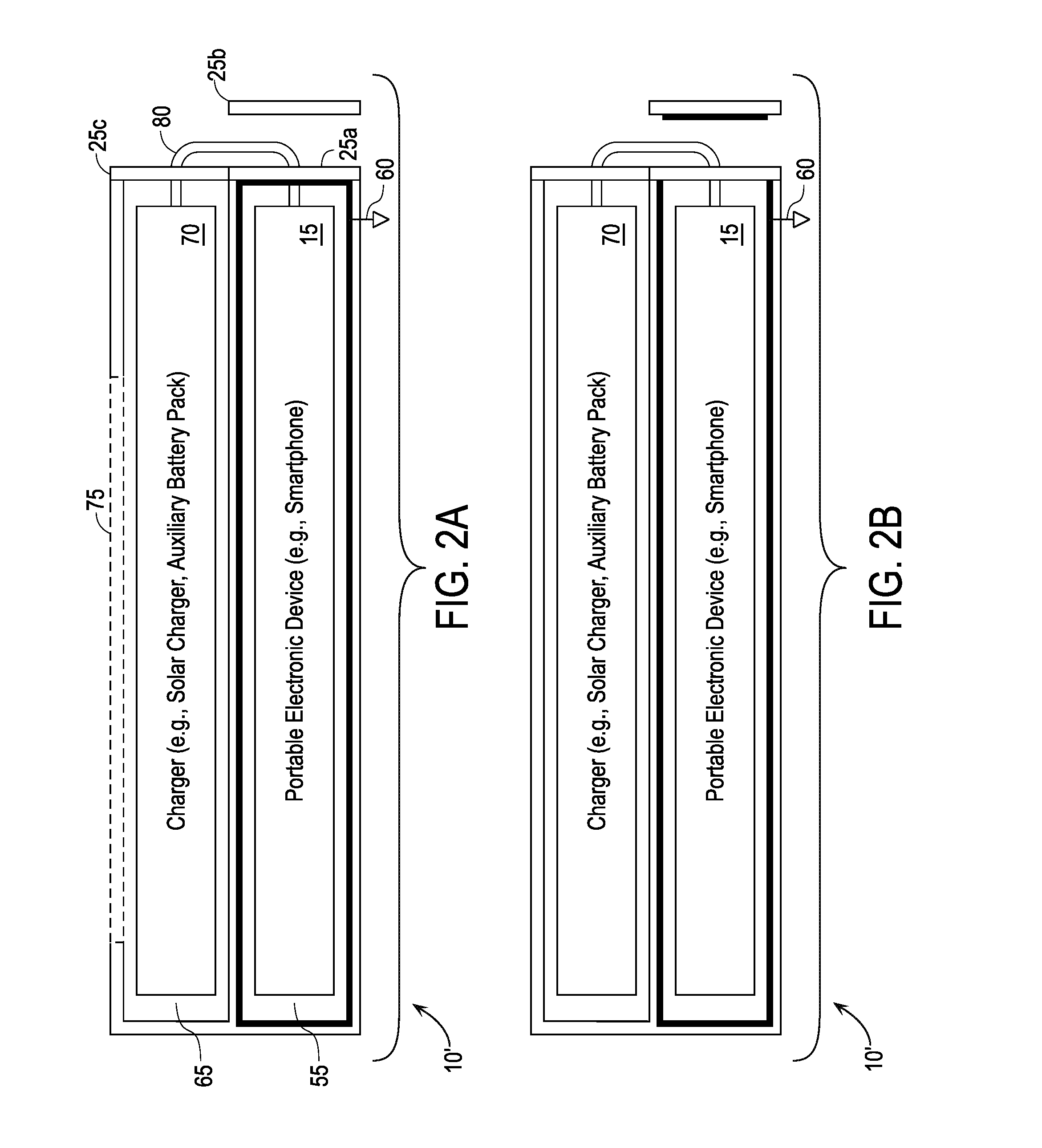
A shield for a portable electronic device includes a pouch with an opening sized to accommodate the portable device and a flap. The pouch includes shielding material inside the pouch and on the flap. When the flap is closed, the shielding material inside the pouch and the shielding material on the flap together substantially surround the device, thereby substantially preventing RF signals emitted by the device from leaving the shield, and further substantially preventing RF signals impinging on the shield from outside from reaching the device. When the flap is open, the shielding material inside the pouch and the shielding material on the flap leave a gap, thereby allowing RF signals emitted by the device to leave the shield, and further allowing RF signals impinging on the shield from outside to reach the device. The shield further includes a compartment for a charger and one or more power cord adapters.

Description

CROSS-REFERENCE TO RELATED APPLICATIONS[0001]This application claims priority to, and incorporates by reference for all purposes the entire disclosures of, the following U.S. provisional applications:[0002]U.S. Patent Application No. 61 / 736,385, filed Dec. 12, 2012, for “Radiation-Blocking Case for Hand-Held Electronic Device” (inventor Paul F. Davis); and[0003]U.S. Patent Application No. 61 / 589,154, filed Jan. 20, 2012, for “Leather Cell Phone Case / RF Signal Blocking Device / Electromagnetic Radiation Shielding Device” (titled in the original cover sheet as “The Wisephone case, is for enclosing a cell phone. It blocks RF signals to and from the device and blocks all electromagnetic radiation that may emanate from the cell phone. Made of a leather exterior; belt clip; an mid-lining of aluminized polyurethane; an inner bag of plus fabric; a Solar Cell phone charger; five different power adapters, that snap onto a plastic form mold. It has an opening at the top end, a back flap that fol...

Claims


Application Information

Patent Timeline
Patent Type & Authority Applications(United States)
IPC IPC(8): H05K9/00H01R27/02
CPCH05K9/0007H01R27/02H04B1/3888H01R31/06H01R13/72H05K9/0043H05K9/0045
Inventor DAVIS, PAUL FITZGERALD
Owner DAVIS PAUL FITZGERALD
Learn More