

Gravity sedimentation process and apparatus
- Summary
- Abstract
- Description
- Claims
- Application Information
AI Technical Summary
Benefits of technology
Problems solved by technology
Method used
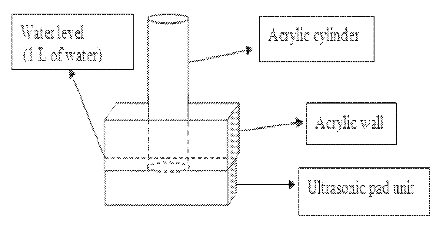
Image

Examples
example 1
Ultrasonic Treatment in the Transition Zone within the Hindered Settling Zone
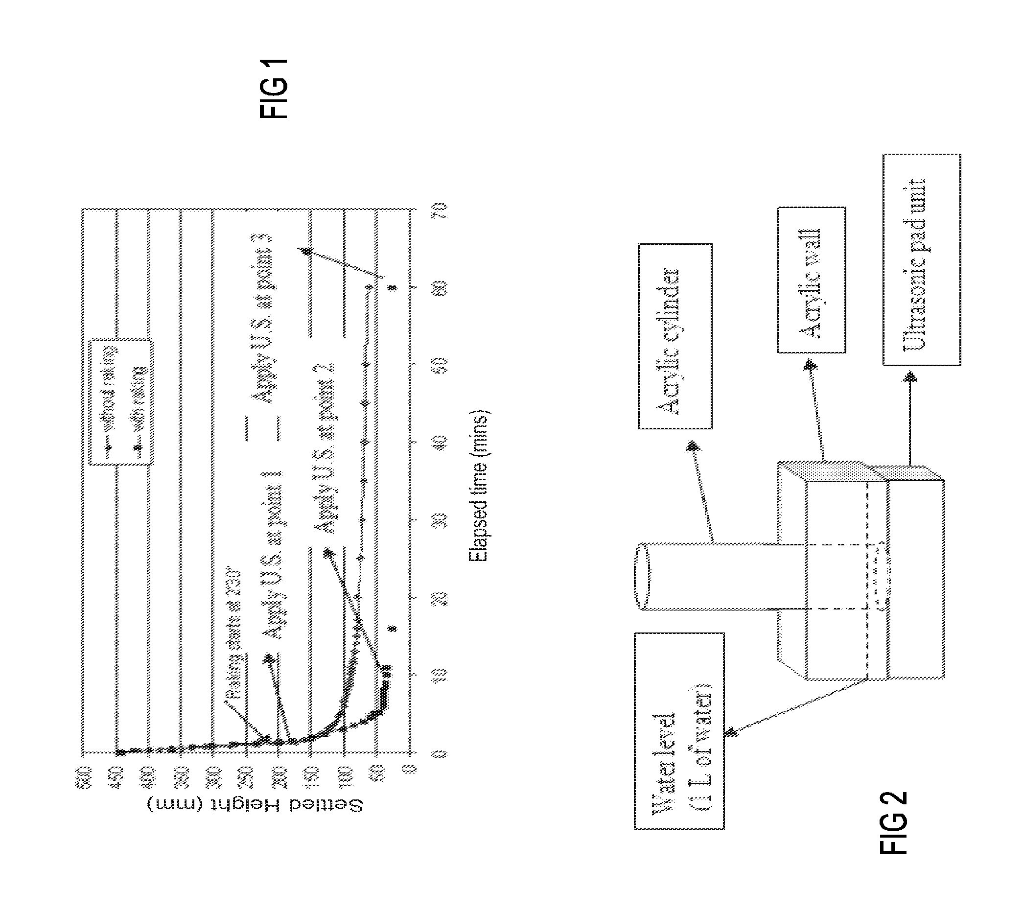
[0071]When settling reached Point 2 in FIG. 1, the settled bed was mostly solidified by raking and the flocs were forming a self-supporting honeycomb structure. In order to collapse this self-supporting structure and further compress the flocs, ultrasonic treatment was applied at an effective power level, being a power level just below the power level which first disperses the settled bed. The ultrasonic treatment was applied with continuous raking.
[0072]For System 1, based on the results of the above power level testing, the ultrasonic treatment was applied at Power Level 2 (with a calculated intensity of 2.01 W / l in the acrylic cylinder) after 10 minutes of raking. The ultrasonic duration varied from 1 min to 12 min.
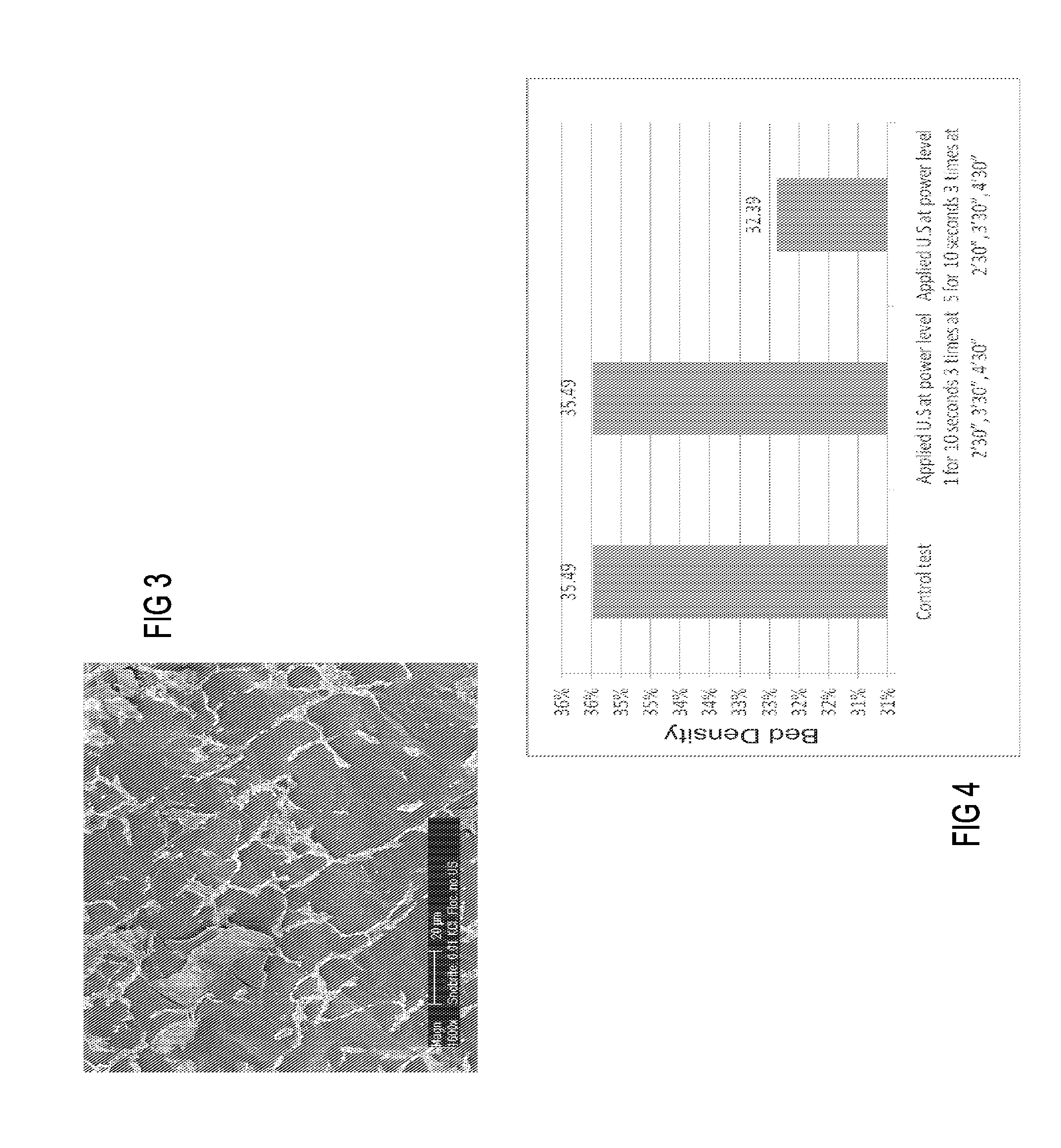
[0073]The results of the application of the ultrasonic treatment in the transition zone showed strong dependence on time. The bed density increased by up to 3.76% after 2.5 minutes of treatmen...
PUM
| Property | Measurement | Unit |
|---|---|---|
| Frequency | aaaaa | aaaaa |
| Power density | aaaaa | aaaaa |
| Power density | aaaaa | aaaaa |
Abstract
Description
Claims
Application Information