Armature shaft bearing unit

a technology of shaft bearings and armatures, which is applied in the field of armatures, can solve problems such as limit the movement, and achieve the effects of saving time and assembly effort, saving cost and installation space, and high ease of operation

Inactive Publication Date: 2013-08-15
ROBERT BOSCH GMBH
View PDF10 Cites 15 Cited by
  • Summary
  • Abstract
  • Description
  • Claims
  • Application Information

AI Technical Summary

Benefits of technology

[0008]In addition it is proposed that the at least one damping element is at least substantially designed to damp vibrations of the armature shaft during operation in a direction at least substantially perpendicular to a rotational axis of the armature shaft. By “at least substantially designed to” should here be understood, in particular, a special arrangement of a component to fulfill a primary function of the component, wherein a geometry, a material and further parameters of the component which appear sensible to the person skilled in the art are arranged specifically to fulfill the primary function. The term “substantially perpendicular” is here meant to define, in particular, an orientation of a direction relative to a reference direction, wherein the direction and the reference direction form an angle of 90° and the angle has a maximum deviation of, in particular, less than 8°, advantageously less than 5°, and particularly advantageously less than 2°. It is also conceivable, however, that the damping element, in addition to the damping of vibrations of the armature shaft in the direction perpendicular to the rotational axis of the armature shaft, damps vibrations of the armature shaft during operation in a direction along an axial extent of the armature shaft. By a “rotational axis” should here be understood, in particular, an axis of the armature shaft about which the armature shaft, during operation, is rotatably mounted. By means of the inventive design of the armature shaft bearing unit, vibrations of the armature shaft which impact upon an operator can be damped particularly advantageously via the housing. Particularly advantageously, high ease of operation can be achieved.
[0009]It is further proposed that the armature shaft bearing unit comprises at least two damping elements, which are arranged one behind the other in a peripheral direction. By a “peripheral direction” should here be understood, in particular, a direction which runs around the armature shaft in a plane perpendicular to the rotational direction of the armature shaft. Particularly preferably, the at least two damping elements are arranged distributed evenly, in particularly symmetrically, along the peripheral direction. A specific arrangement of the damping elements onto a particularly vibration-intensive direction of a machine component, in particular the armature shaft, can advantageously be achieved.
[0010]In addition it is proposed that the armature shaft bearing unit has at least one bearing element and at least one bearing receiving element, which latter is disposed in at least one damping direction between the bearing element and the damping element. By a “bearing receiving element” should here be understood, in particular, a component in which at least one bearing element is arranged in a mounted state and which transmits forces radiating from the bearing element, in particular radial forces, in the direction of the housing, so that a force flow from the armature shaft to the b

Problems solved by technology

It is also conceivable, however, that the damping element itself serves as a stop, in particular if the damping element is configured as a helical spring, in

Method used


Image

  • Armature shaft bearing unit
  • Armature shaft bearing unit
  • Armature shaft bearing unit

Examples


Embodiment Construction

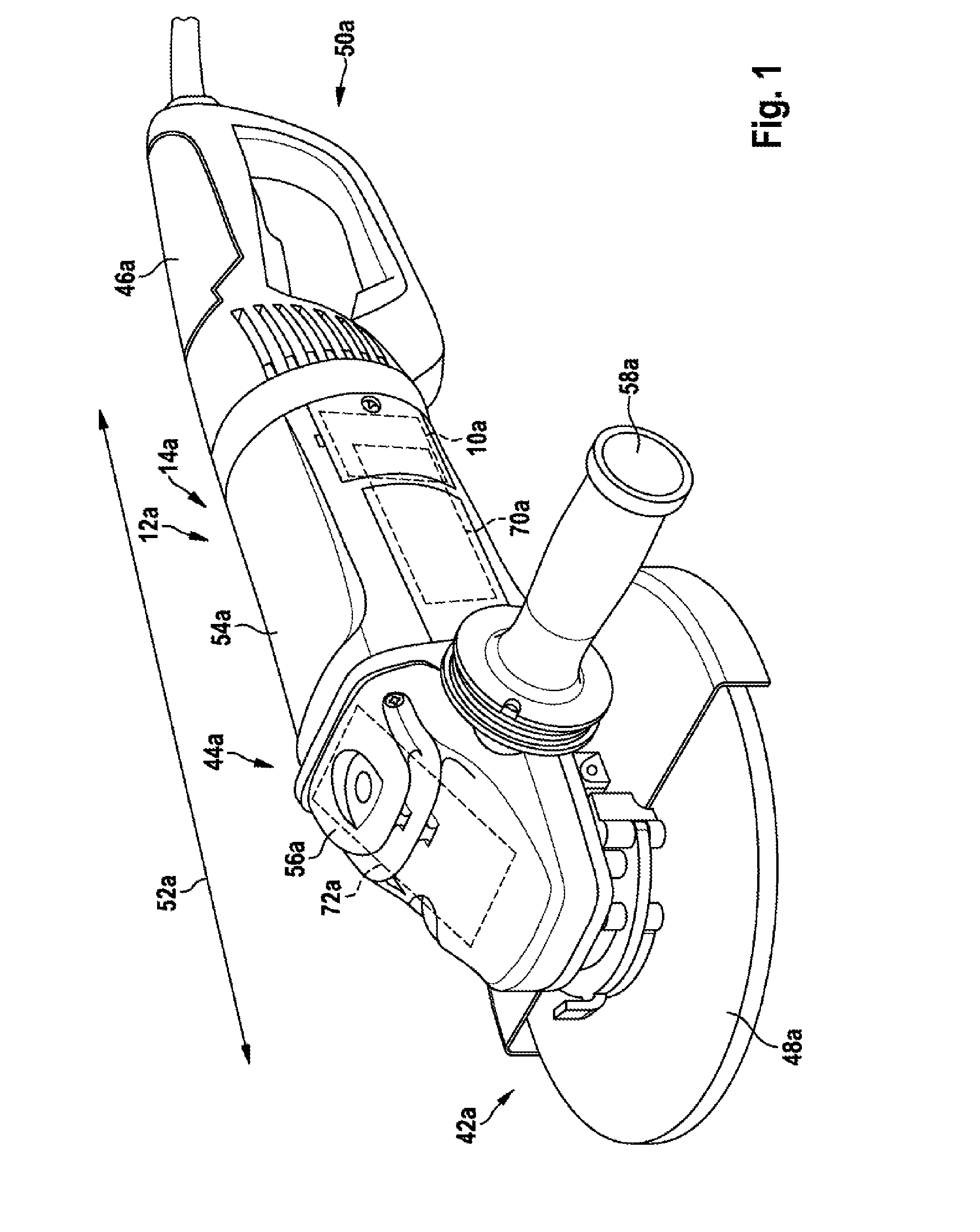
[0031]FIG. 1 shows a portable power tool 12a configured as an angle grinder 14a and having an armature shaft bearing unit 10a. The angle grinder 14a comprises a protective hood unit 42a, a housing unit 44a and a main handle 46a, which extends, on a side 50a facing away from a tool 48a, in the direction of a direction of principal extent 52a of the angle grinder 14a. The housing unit 44a comprises a motor housing 54a for receiving an electric motor 70a and a gear housing 56a for receiving a gear mechanism 72a. On the gear housing 56a is disposed an auxiliary handle 58a for the guidance of the angle grinder 14a. The auxiliary handle 58a extends transversely to the direction of principal extent 52a of the angle grinder 14a.

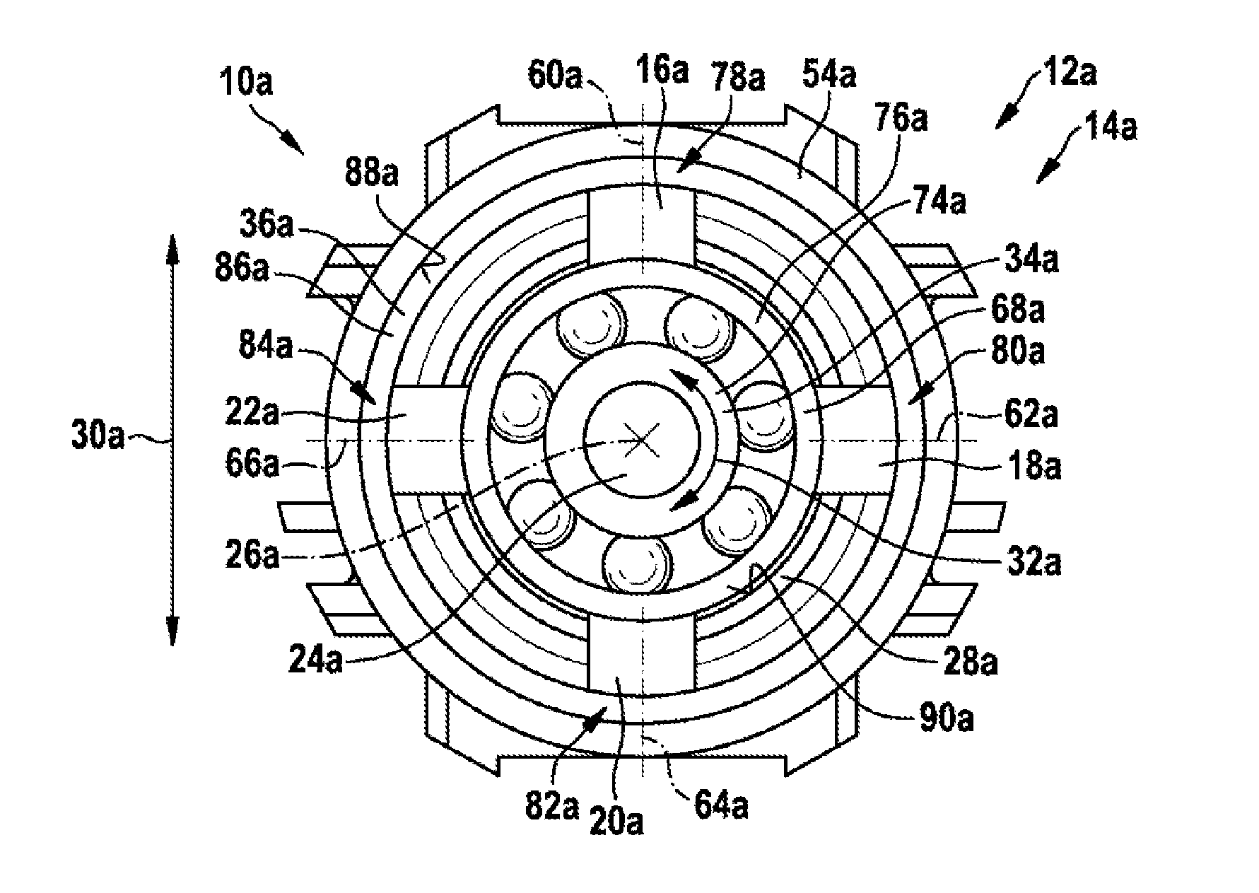
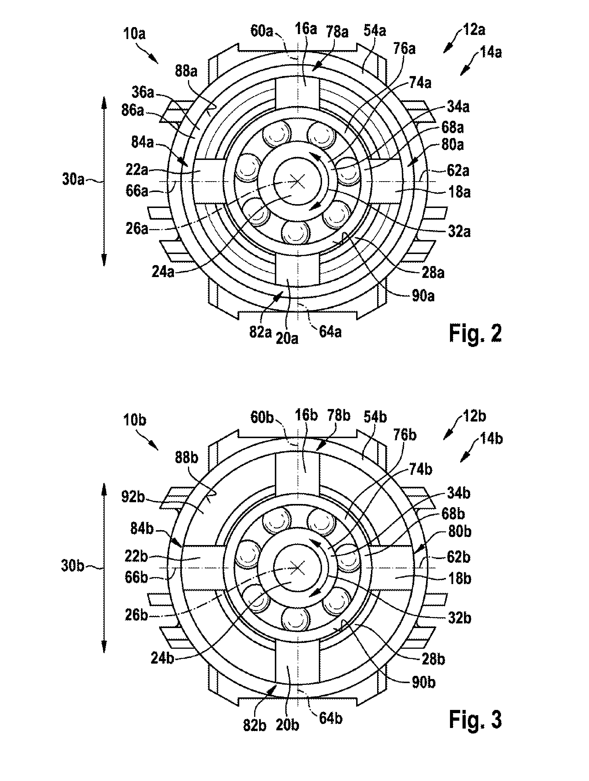
[0032]FIG. 2 shows a detailed view of a first illustrative embodiment of the armature shaft bearing unit 10a disposed in the housing unit 44a. The armature shaft bearing unit 10a is disposed in the motor housing 54a on a side of an armature shaft 24a of the electric...


PUM


Abstract

An armature shaft bearing unit, particularly for an angle grinding machine, includes at least one damping element configured to damp vibrations of an armature shaft. The armature shaft bearing unit further includes at least one movement limiting element configured to limit a movement of the armature shaft in at least one damping direction of the at least one damping element.

Description

PRIOR ART[0001]Armature shaft bearing units for portable power tools, comprising a damping element for damping vibrations of an armature shaft, are already known.DISCLOSURE OF THE INVENTION[0002]The invention is based on an armature shaft bearing unit for a portable power tool, in particular for an angle grinder, comprising at least one damping element which is designed to damp vibrations of an armature shaft.[0003]It is proposed that the armature shaft bearing unit has at least one motion limiting element, which is designed to limit a motion of the armature shaft in at least one damping direction of the at least one damping element. By an “armature shaft bearing unit” should here be understood, in particular, a bearing unit for the armature shaft, which bearing unit rotatably supports the armature shaft in a housing of a portable power tool. Preferably, the armature shaft bearing unit, in a mounted state of the armature shaft in a housing of a portable power tool, in particular an ...

Claims


Application Information

Patent Timeline
IPC IPC(8): F16F15/12F16C33/30
CPCB24B23/028B24B41/007B25F5/006F16F15/1201H02K5/24H02K7/145F16C33/30H02K5/1732F16C19/06F16C27/066F16C2380/26
Inventor SCHADOW, JOACHIMANDRASIC, SINISASCHULLER, MARCUS
Owner ROBERT BOSCH GMBH
Why Eureka
Try Eureka