Detecting broadside and directional acoustic signals with a fiber optical distributed acoustic sensing (DAS) assembly

a distributed acoustic sensing and fiber optic technology, applied in the direction of vibration measurement in solids, instruments, specific gravity measurement, etc., can solve the problems of radial strain on the fiber, the cable becomes much less sensitive to the signal, and the signal may even fail to d

Active Publication Date: 2013-08-15
SHELL USA INC
View PDF11 Cites 33 Cited by
  • Summary
  • Abstract
  • Description
  • Claims
  • Application Information

AI Technical Summary

Benefits of technology

[0011]Some embodiments of the invention include a fiber optic cable comprising a first fiber having a first coating and a second fiber having a second coating, wherein the first and second coatings are selected such that the Young's Modulus or Poisson's ratio of the first coated fiber is less than the Young's Modulus or Poisson's ratio of the second coated fiber. This fiber can be used to advantage in a method for creating an image of a subsurface, locating microseisms, or the like, or in-well. The method comprises the steps of a) deploying the fiber optic cable, b) transmitting a seismic signal into the subsurface, c) recording a first data set on the first fiber and a second data set on the second fiber, wherein the data sets include signals received as a result of the seismic signal in step b), d) adjusting at least a portion of the first data set with at least a portion of the second data set so as to obtain an output data set that is indicative of the portions of received signals travelling through the sub

Problems solved by technology

While there exists a variety of commercially available DAS systems that have varying sensitivity, dynamic range, spatial resolution, linearity, etc., all of these systems are primarily sensitive to axial strain as the angle between direction of trav

Method used


Image

  • Detecting broadside and directional acoustic signals with a fiber optical distributed acoustic sensing (DAS) assembly
  • Detecting broadside and directional acoustic signals with a fiber optical distributed acoustic sensing (DAS) assembly
  • Detecting broadside and directional acoustic signals with a fiber optical distributed acoustic sensing (DAS) assembly

Examples


example

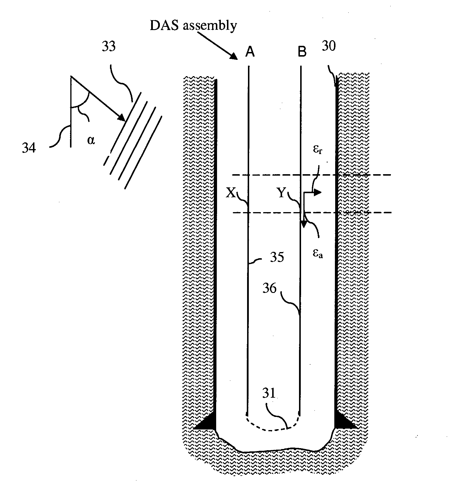
[0044]In a hypothetical example, a first cable segment A includes an outer shell constructed of PVC, which is relatively stiff (Young's modulus 3 GPa) and quite light. Between the PVC and the cable, is left empty. Strains in the formation will not be effectively transferred to the cable in this segment, so it represents the part of the cable with a “low Poisson's Ratio” coating. In another segment of the same cable, B, the cable is embedded in rubber, which has a very high Poisson's ratio and is very compressible. If it were sufficiently bonded to the cable, the rubber would be expected to cause significant axial strain on the cable when impacted by a broadside wave. The PVC can be installed in the field from two halves with watertight caps on the ends allowing the cable to pass through. The entire composite cable is preferably placed in a trench and water would be added so that it would end up encased in ice (Y=9 GPa), or other suitable material, such as cement, so as to ensure goo...


PUM


Abstract

A Distributed Acoustic Sensing (DAS) fiber optical assembly comprises adjacent lengths of optical fiber A, B with different directional acoustic sensitivities, for example by providing the first length of optical fiber A with a first coating 35, such as acrylate, and the second length of optical fiber B with a second coating 36, such as copper, wherein the first and second coatings 35 and 36 may be selected such that the Poisson's ratio of the first length of coated fiber A is different from the Poisson's ratio of the second length of coated fiber B. The different Poisson's ratios and/or other properties of the adjacent lengths of optical fiber A and B improve their directional acoustic sensitivity and their ability to detect broadside (radial) acoustic waves.

Description

FIELD OF THE INVENTION[0001]The invention relates to fiber optic devices and in particular to a fiber optical Distributed Acoustic Sensing (DAS) assembly adapted to sense the magnitude and direction of acoustic signals that are travelling at an angle or substantially perpendicular to the device.BACKGROUND OF THE INVENTION[0002]Various attempts have been made to provide sensing capabilities in the context of petroleum exploration, production, and monitoring, with varying degrees of success. Recently, these attempts have included the use of fiber optic cables to detect acoustic energy. Because the cables typically comprise optically conducting fiber containing a plurality of backscattering inhomogeneities along the length of the fiber, such systems allow the distributed measurement of optical path length changes along an optical fiber by measuring backscattered light from a laser pulse input into the fiber. Because they allow distributed sensing, such systems may be referred to as “di...

Claims


Application Information

Patent Timeline
IPC IPC(8): G01V1/34G01H9/00
CPCG01H9/004G01N2291/044G01N29/2418
Inventor MESTAYER, JEFFERY JOSEPHWILLS, PETER BERKELEY
Owner SHELL USA INC
Why Eureka
Try Eureka