Exhaust gas sensor module

a technology of exhaust gas and sensor module, which is applied in the direction of instruments, machines/engines, mechanical equipment, etc., can solve the problems of harmful diesel particulate matter and soot present in exhaust gas, the current available scr system suffers from several drawbacks, and cannot meet the emission level with improved combustion technology

Inactive Publication Date: 2013-08-22
CUMMINS INTPROP INC
View PDF6 Cites 43 Cited by
  • Summary
  • Abstract
  • Description
  • Claims
  • Application Information

AI Technical Summary

Benefits of technology

[0009]The subject matter of the present application has been developed in response to the present state of the art, and in particular, in response to the problems and needs in the fluid sensing art that have not yet been fully solved by currently available sensors and sensing syst...

Problems solved by technology

For example, the regulated emissions of NOx and particulates from diesel-powered internal combustion engines are low enough that, in many cases, the emissions levels cannot be met with improved combustion technologies.
The substrate of the DPF filters harmful diesel particulate matter and soot present in the exhaust gas.
However, due to the undesirability of handling pure ammonia, most systems utilize an alternate compound such as urea, which vaporizes and decomposes to ammonia before entering the SCR catalyst.
However, currently available SCR systems also suffer from several drawbacks.
For example, one known drawback is the inability to effectively provide feedback control of the engine system based on the sensed characteristics of exhaust gas flowing through the SCR system.
Although a control system employing sensors upstream and downstream of an SCR catalyst provides some benefits, the efficiency and accuracy of the system often suffers with such an arrangement.
Addi...

Method used


Image

  • Exhaust gas sensor module
  • Exhaust gas sensor module
  • Exhaust gas sensor module

Examples


Embodiment Construction

[0038]Reference throughout this specification to “one embodiment,”“an embodiment,” or similar language means that a particular feature, structure, or characteristic described in connection with the embodiment is included in at least one embodiment of the present disclosure. Appearances of the phrases “in one embodiment,”“in an embodiment,” and similar language throughout this specification may, but do not necessarily, all refer to the same embodiment. Similarly, the use of the term “implementation” means an implementation having a particular feature, structure, or characteristic described in connection with one or more embodiments of the present disclosure, however, absent an express correlation to indicate otherwise, an implementation may be associated with one or more embodiments.

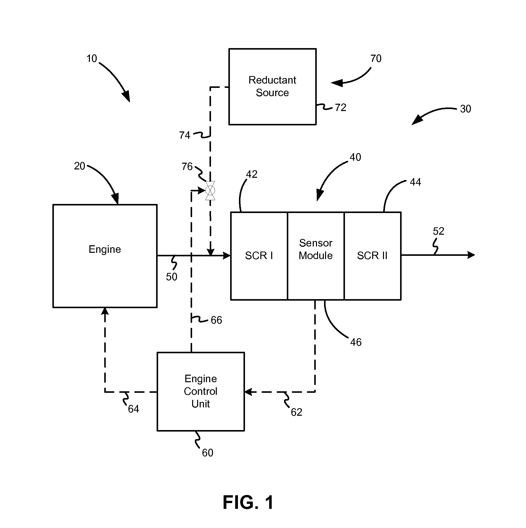
[0039]FIG. 1 depicts one embodiment of an internal combustion engine system 10. The main components of the engine system 10 include an internal combustion engine 20 and an exhaust gas after-treatment syst...


PUM


Abstract

Described herein is a sensor module for sensing characteristics of a fluid flowing through a fluid conduit. The sensor module includes a sample probe with at least one sample arm that extends radially inwardly from a sidewall portion of the fluid conduit to a center portion of the fluid conduit, defines a fluid flow channel, and includes a plurality of inlet apertures. The sample probe also includes a sensor well that is located at a radially outer end of the at least one sample arm. The sensor well defines an interior volume that is in fluid communication with the fluid flow channel, an upstream portion closed to an first portion of the fluid conduit upstream of sensor well, and a discharge aperture open to a second portion of the fluid conduit downstream of the sensor well. The sensor module also includes a sensor positioned in the interior volume.

Description

CROSS-REFERENCE TO RELATED APPLICATION[0001]This application claims the benefit of U.S. Provisional Patent Application No. 61 / 597,574, filed Feb. 10, 2012, and is a continuation-in-part of U.S. patent application Ser. No. 13 / 007,342, filed Jan. 14, 2011, which are incorporated herein by reference.FIELD[0002]This disclosure relates to sensing characteristics of a fluid, and more particularly to a fluid sensor module for sensing characteristics of a flowing fluid.BACKGROUND[0003]Exhaust emissions regulations for internal combustion engines have become more stringent over recent years. For example, the regulated emissions of NOx and particulates from diesel-powered internal combustion engines are low enough that, in many cases, the emissions levels cannot be met with improved combustion technologies. Therefore, the use of exhaust after-treatment systems on engines to reduce harmful exhaust emissions is increasing. Typical exhaust after-treatment systems include any of various component...

Claims


Application Information

Patent Timeline
IPC IPC(8): F01N11/00G01M15/10
CPCF01N11/00G01M15/102G01N1/2252F01N3/2066F01N13/008G01N1/26Y02T10/24F01N2610/148Y02T10/47F01N13/0097F01N13/0093F01N2560/02Y02T10/12Y02T10/40
Inventor MITCHELL, DOUGLAS A.CLERC, JIMLIU, Z. GERALDMANEKAR, ABHISHEKSIMONTON, WILLIAM L.SZAILER, TAMAS
Owner CUMMINS INTPROP INC
Why Eureka
Try Eureka