
Start of injection timing

a fuel injection and timing technology, applied in the direction of machines/engines, electrical control, mechanical equipment, etc., can solve the problems of incomplete combustion, reduced egr rate of exhaust gas recirculation, and unburned hydrocarbons

Active Publication Date: 2013-08-22
INT ENGINE INTPROP CO LLC
View PDF4 Cites 18 Cited by
  • Summary
  • Abstract
  • Description
  • Claims
  • Application Information

AI Technical Summary

Benefits of technology

This patent describes an engine management system that adjusts the timing of starting injection to maintain optimal combustion phasing, despite changes in intake manifold conditions. The system uses correlations of ignition delay, intake manifold pressure, and intake oxygen concentration to determine the compensated start of injection timing. This allows for a more accurate and consistent control of combustion phasing, resulting in improved engine performance. The method can be used with both direct and indirect techniques for measuring the intake manifold pressure and oxygen concentration. Overall, this patent provides a technical solution for controlling combustion timing in engines.

Problems solved by technology

In many engines, exhaust gas recirculation (EGR) rates are decreased during transient operation to avoid engine misfire, usually due to a decreased air to fuel ratio as a result of turbocharger delay.
However, because stricter emission standards do not allow for such decreased EGR rates, attempts are made to shift injection timing to avoid engine misfire.
Under-advanced SOI timing, or delaying start of injection, causes incomplete combustion, produces unburned hydrocarbons and poor fuel efficiency due to late combustion phasing.
Current technology typically advances injection timing significantly during transient operation causing engine misfire.
Overly-advanced SOIs, or injecting before the piston reaches TDC, can result in higher in-cylinder pressure and temperature, and higher efficiency, but also results in elevated engine noise and excess nitrous oxide (NOx) production.

Method used


Image

  • Start of injection timing
  • Start of injection timing
  • Start of injection timing

Examples


Embodiment Construction

[0027]While this invention is susceptible of embodiment in many different forms, there are shown in the drawings, and will be described herein in detail, specific embodiments thereof with the understanding that the present disclosure is to be considered as an exemplification of the principles of the invention and is not intended to limit the invention to the specific embodiments illustrated.

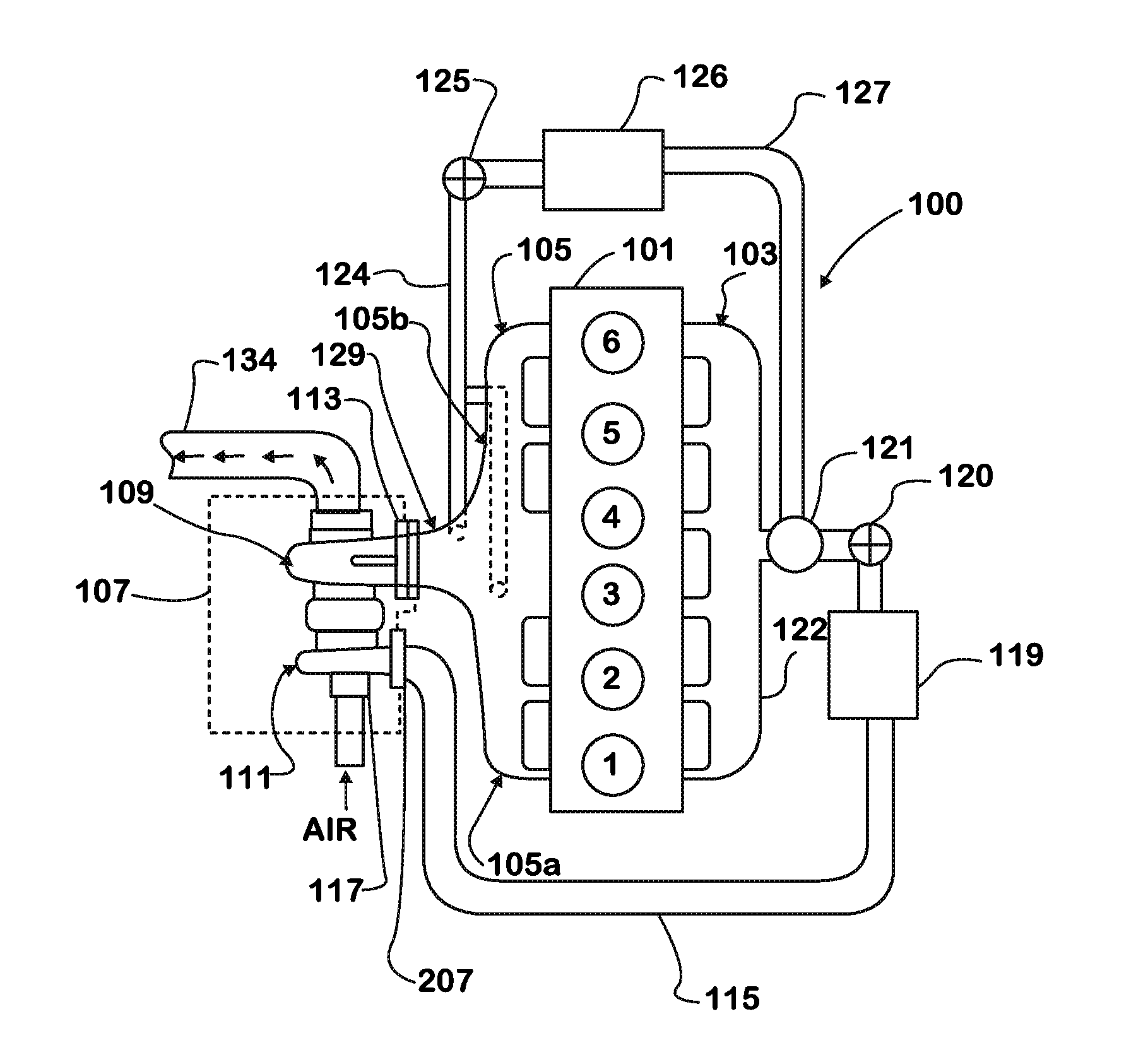
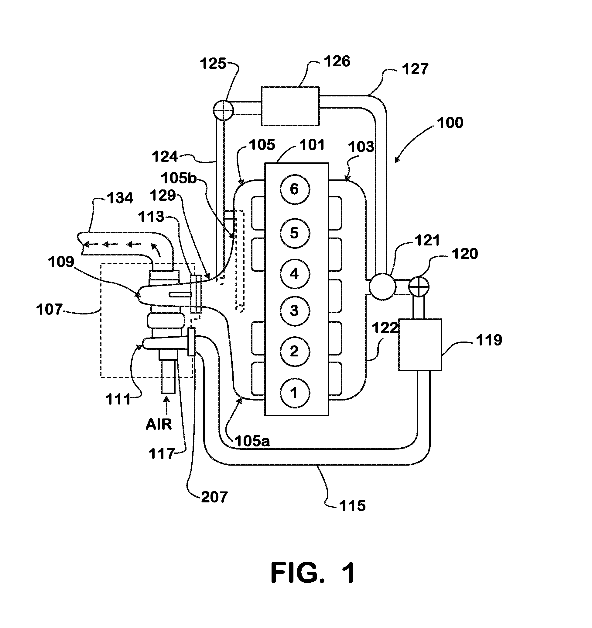
[0028]An engine 100 is shown schematically in FIG. 1. The engine 100 has a block 101 that includes a plurality of cylinders. The cylinders in the block 101 are fluidly connected to an intake system 103 and to an exhaust system 105. The exhaust system includes a first pipe 105a from cylinders 1, 2 and 3 of one bank of cylinders and a second pipe 105b from cylinders 4, 5 and 6. Although an inline arrangement of six cylinders is illustrated, inline or V-arrangements or other arrangements of plural cylinders of any number of cylinders are also encompassed by the invention.

[0029]A turbocharger 107 inc...


PUM


Abstract

A method for controlling fuel injection timing into a cylinder of an internal combustion engine having an internal control system based on ignition delay correlation wherein intake manifold pressure and oxygen concentration values are compared to steady state values of manifold pressure and oxygen concentration of a particular indicated torque set-point and engine speed. Comparing intake manifold pressure and oxygen concentration to steady state reference values further comprises experimentally determining exponential factors for intake manifold pressure factor and oxygen concentration factors. A multiplier for intake manifold pressure and oxygen concentration is determined taking into consideration the exponential factors for manifold pressure and oxygen concentration. An equation for correlation ignition delay is used to determine optional SOI timing.

Description

FIELD OF THE INVENTION[0001]This invention relates to internal combustion engines, including but not limited to the timing of fuel injection.BACKGROUND OF THE INVENTION[0002]Most modern diesel engines, particularly diesel engines for large tractor-trailer trucks, use fuel injectors to deliver a desired fuel charge to an engine cylinder. The fuel injector is a nozzle which injects fuel, atomized by forcibly pumping fuel through the nozzle at high pressure, directly into the combustion chamber of each cylinder. A fuel injector, particularly a fuel injector for use with a diesel engine, is required to accurately discharge a quantity of fuel into a combustion chamber of an internal combustion engine over a wide range of engine operating conditions.[0003]Fuel is injected into the combustion chamber during the final stage of compression. The high degree of compression heats the air such that the heat initiates combustion of the fuel when the fuel is injected into the chamber. The fuel inj...

Claims


Application Information

Patent Timeline
Patent Type & Authority Applications(United States)
IPC IPC(8): F02D41/00
CPCF02D41/144F02D41/1454F02D41/00F02D2200/0406Y02T10/44F02D41/401Y02T10/40
Inventor KUMAR, RAJDE OJEDA, WILLIAMPOPP, JAMES RYNOLD
Owner INT ENGINE INTPROP CO LLC
Learn More