
Ignition device and method of producing super hydrophilic membrane to be used in ignition device

a super hydrophilic membrane and ignition device technology, which is applied in the direction of sparking plugs, engine components, electrical apparatus, etc., can solve the problems of reducing the stability of the ignition plug, reducing the optical transmission properties of the pulse laser, and reducing the electrical insulation between electrodes, so as to promote the oxidative decomposition of oil mist, improve the structure, and remove the oil mist easily

Active Publication Date: 2017-12-28
DENSO CORP
View PDF0 Cites 7 Cited by
  • Summary
  • Abstract
  • Description
  • Claims
  • Application Information

AI Technical Summary

Benefits of technology

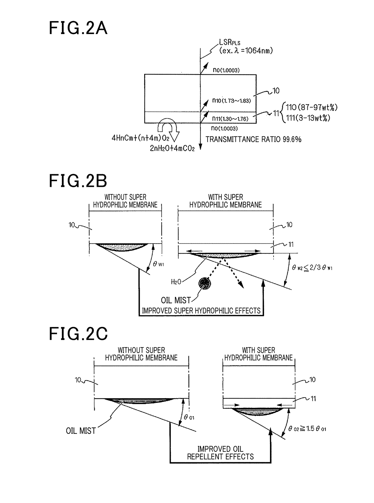
The patent describes an ignition device that uses a super hydrophilic membrane to remove oil and carbon from the surfaces of the optical window and insulator of the ignition plug. The membrane is heated by the combustion of fuel gas, which promotes the oxidative decomposition of the oil and carbon particles. This helps to maintain the combustion window of the combustion chamber for a long period of time. The improved structure of the device also makes it easy to remove the oil and carbon from the optical window.

Problems solved by technology

When a deposit is accumulated on the surface of the optical window due to the oil mist, the optical transmission properties of the pulse laser are reduced due to the deposition of such oil mist, and the presence of the deposit reduces the stable ignition capability of the ignition plug.
Further, for example, when an engine starts and an ordinary spark ignition plug operates at a low temperature and a liquid fuel is burned in incomplete combustion, soot, etc. are generated due to the incomplete combustion, and a deposit is accumulated due to such soot on a surface of an insulation glass in the ordinary ignition plug.
Because the deposit is made of carbon having a conductivity, the formation of deposit reduces the electrical insulation between electrodes of the ignition plug, and deteriorates the stable ignitability of the ignition plug.

Method used


Image

  • Ignition device and method of producing super hydrophilic membrane to be used in ignition device
  • Ignition device and method of producing super hydrophilic membrane to be used in ignition device
  • Ignition device and method of producing super hydrophilic membrane to be used in ignition device

Examples


first exemplary embodiment

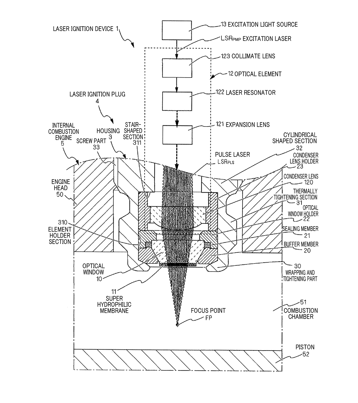
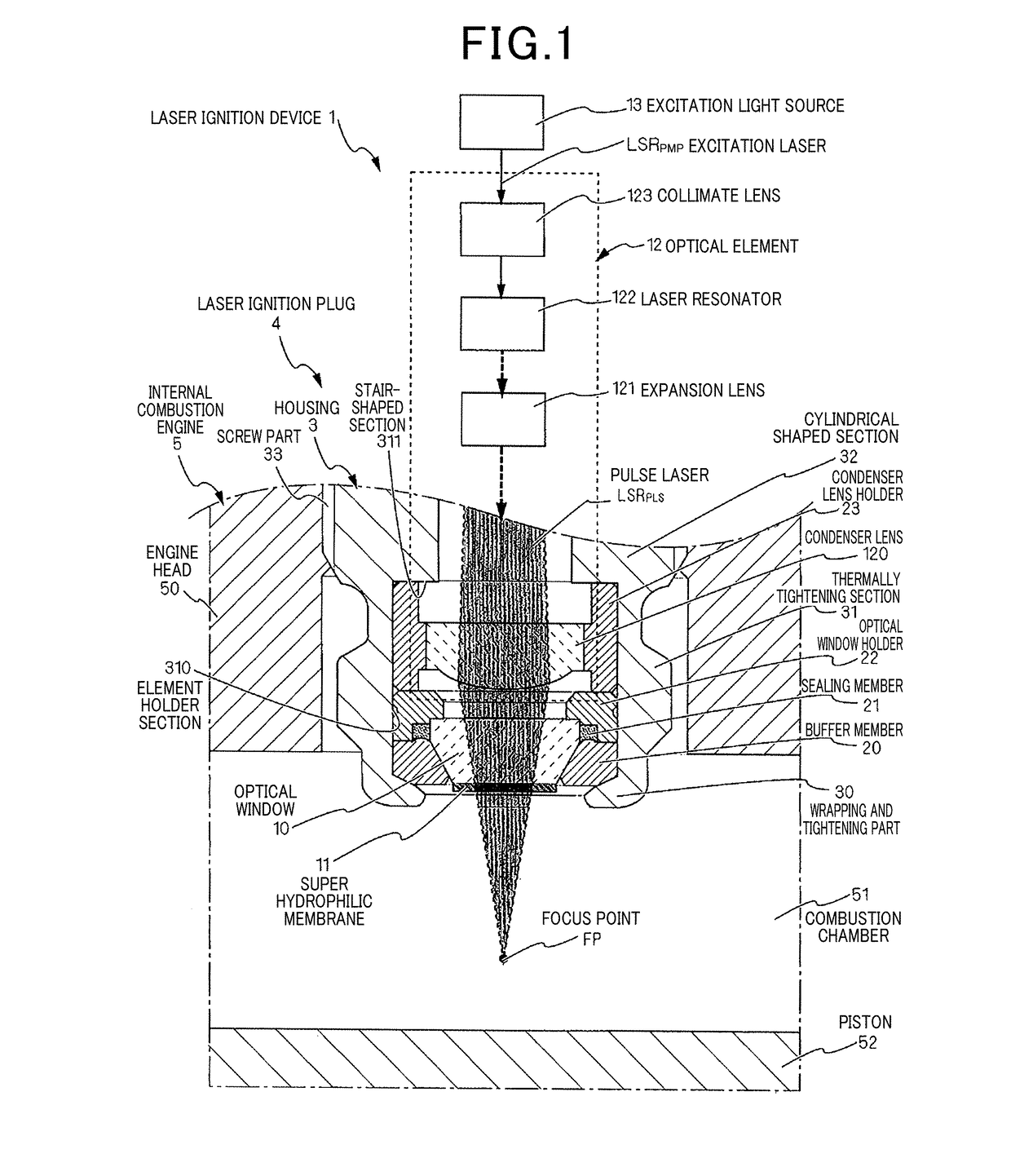
[0038]Next, a description will be given of the ignition device according to the first exemplary embodiment of the present invention with reference to FIG. 1.

[0039]The ignition device according to the first exemplary embodiment is a laser ignition device 1 with a laser ignition plug 4. The laser ignition plug 4 is mounted in a wall of a combustion chamber 51 of an internal combustion engine 5. The internal combustion engine 5 has an engine head part (a combustion engine wall) 50, cylinders (not shown) and pistons 52. The engine head part 50 covers the upper surfaces of the cylinders. The pistons 52 move vertically in the cylinders. A combustion chamber 51 is formed by the cylinder and the piston 52. A fuel mixture gas is introduced into the combustion chamber 51. The fuel mixture gas is burned in the cylinders to create heat energy, and the fuel mixture gas expands in the cylinders to create a potential energy. The piston 52 converts the generated potential energy to mechanical power...

second exemplary embodiment

[0097]Hereinafter, a description will be given of the ignition device according to the second exemplary embodiment with reference to FIG. 4 to FIG. 12.

[0098]The ignition device according to the second exemplary embodiment is a spark ignition device 6. The spark ignition device 6 has a spark ignition plug 60 as the ignition plug mounted in the wall of the combustion chamber 51. The internal combustion engine 5 to which the spark ignition device 6 is applied has the same structure of the internal combustion engine 5 used in the first exemplary embodiment previously described. Accordingly, the same components will be designated by the same reference numbers and characters, and the explanation of the same components is omitted for brevity. The different between the second exemplary embodiment and the first exemplary embodiment will be explained.

[0099]The spark ignition device 6 is composed of the spark ignition plug 60 and a power supply section 8 which supplies electric power to the sp...

experimental example

[0114]A description will be given of the experiments of the spark ignition device 6 having the structure shown in FIG. 4.

[0115]In the experiments, the spark ignition plug 60 was produced by using the following method, in which the outer surface of the insulator 7 was covered with the super hydrophilic membrane 11.

[0116]In the spark ignition plug 60, the super hydrophilic membrane 11 was continuously formed from the intermediate section 72 of the insulator to the front end surface having a ring shape of the insulator 7 through the outer surface having a tapered shape at the front end side of the insulator 7. The super hydrophilic membrane 11 formed on the distal end side of the insulator 7 had an outer diameter of 6.4 mmφ, the super hydrophilic membrane 11 formed on the front end side of the insulator 7 had an outer diameter of 4.2 mmφ. The super hydrophilic membrane 11 had an axial length of 13.2 mm. The housing 63, which faces the super hydrophilic membrane 11, had an inner diamete...


PUM


Abstract

In an ignition device having an ignition plug for igniting a fuel mixture gas introduced in a combustion chamber, a super hydrophilic membrane is formed on a surface at the combustion chamber side of a plug forming member of the ignition plug. The super hydrophilic membrane contains super hydrophilic particles and thermal excitation catalyst particles, and satisfies a relationship of θW2<θW1, where θW1 indicates a water contact angle between water and the plug forming member on which no super hydrophilic membrane is formed, and θW2 indicates a water contact angle between water and the plug forming member on which the super hydrophilic membrane is formed.

Description

TECHNICAL FIELD[0001]The present invention relates to ignition devices for igniting a fuel mixture gas introduced into a combustion chamber of an internal combustion engine, and in particular, relates to ignition devices having an ignition plug, on a surface of which a super hydrophilic membrane is formed and coated. The formation of the super hydrophilic membrane prevents a deposit from adhering on the surface of the ignition plug, and provides the ignition plug having a stable ignitability. The present invention further relates to a method of producing such super hydrophilic membranes to be used in the ignition devicesBACKGROUND ART[0002]Recently, there have been various studies and development regarding laser ignition devices to be applied to gaseous fuel engines to be used for cogeneration, and to be applied to internal combustion engines of poor ignition performance such as lead burn fuel mixture engines, etc. The laser ignition device has a semiconductor laser as an excitation...

Claims


Application Information

Patent Timeline
Patent Type & Authority Applications(United States)
IPC IPC(8): H01T13/14F02P23/04
CPCH01T13/14F02P23/04
Inventor KANEHARA, KENJISUGIURA, AKIMITSU
Owner DENSO CORP
Learn More