
Gas flare useful for combusting landfill gas emissions

a landfill gas and flare technology, applied in the field of gas combustion, can solve the problems of high cost, frequent burning of gas, and unpleasant smell of gas, and achieve the effect of reducing the number of flares

Active Publication Date: 2020-01-07
BRANNON LINWOOD THAD
View PDF30 Cites 0 Cited by
  • Summary
  • Abstract
  • Description
  • Claims
  • Application Information

AI Technical Summary

Benefits of technology

This patent describes a gas flare that can safely and efficiently handle low flows of landfill gas. The gas flare has a unique design that includes a burner tube, an updraft shield, a windshield tube, and a cover plate. The gas flare can be used at landfills or other gas flow conduits and is well-suited for low gas flow rates. It provides a safer, more efficient solution for handling landfill gas.

Problems solved by technology

This gas often has an unpleasant smell and typically includes methane, carbon dioxide, and other constituents, such as hydrogen sulfide and complex hydrocarbons.
Landfill gas may cause severe odor problems.
While passive flares can be cost effective they routinely burn out.
Because such passive flares are positioned proximate to the landfill vents to minimize the use of lengthy gas pipe runs, the flares are usually located in remote locations where it is difficult to monitor the presence of a flame.
It is very inconvenient to manually re-ignite the flares when the flame is extinguished.
During any time in which the flame is out, the gas is permitted to escape into the atmosphere, creating potentially lengthy periods in which the odor is not being treated.
Construction and demolition (C&D) landfills typically do not produce a lot of combustible gas because they do not contain as much organic content compared to Class 3 and Class 1 facilities that typically receive large quantities of organic waste.
In particular, conventional open air / open top / perforated flares are highly susceptible to wind and precipitation.
Such problems commonly occur when low combustible gas flow rates exist, which is a common condition at C&D landfills.

Method used


Image

  • Gas flare useful for combusting landfill gas emissions
  • Gas flare useful for combusting landfill gas emissions
  • Gas flare useful for combusting landfill gas emissions

Examples


Embodiment Construction

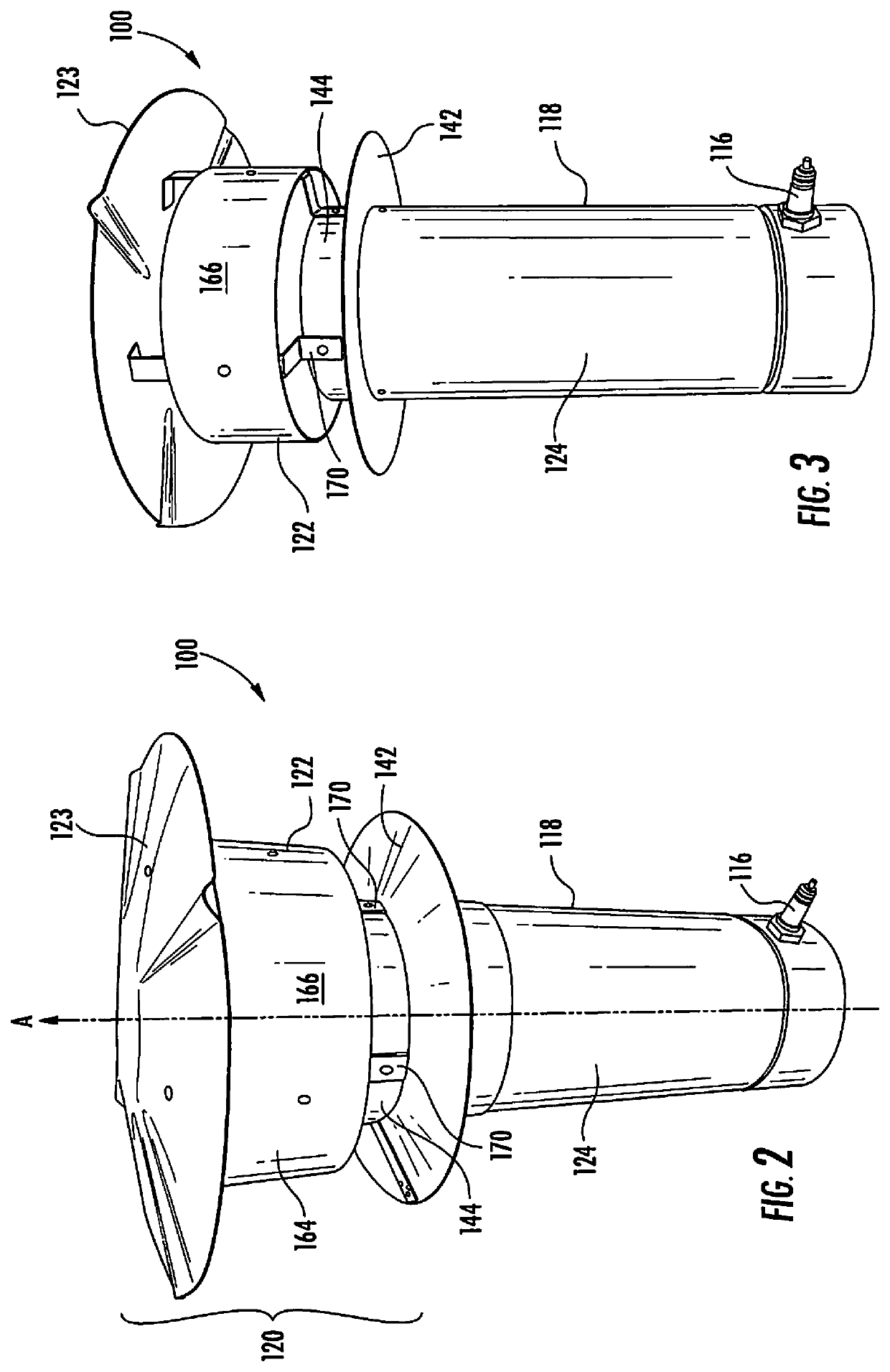
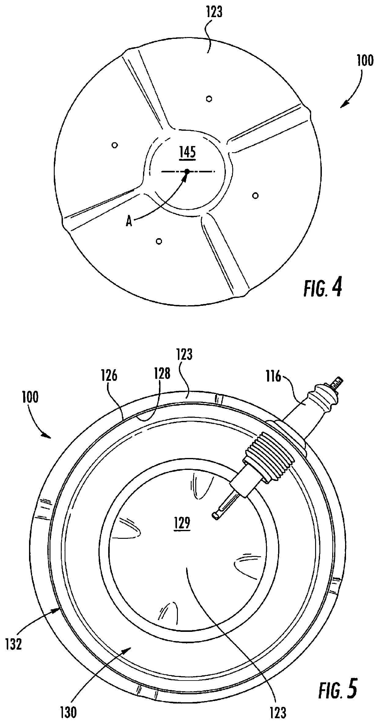
[0025]Exemplary embodiments are now described by referring to the drawings. Where a particular feature is disclosed in the context of a particular embodiment, that feature can also be used, to the extent possible, in combination with and / or in the context of other embodiments. The apparatus and methods may be embodied in many different forms and should not be construed as limited to only the embodiments described here or shown in the drawings.

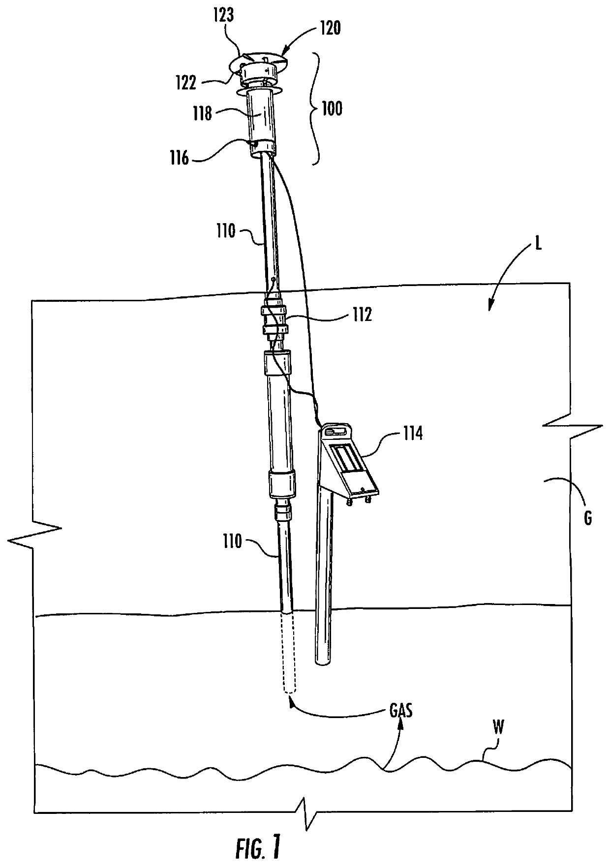
[0026]Referring to FIG. 1, an example embodiment of the gas flare apparatus 100 is shown installed in a landfill L environment having waste W buried beneath the ground G. The waste W generates combustible gas such as methane, which the gas flare apparatus 100 burns to prevent the gas from entering the atmosphere.

[0027]The gas flare apparatus 100 may be used in many different environments other than landfills, but its use is described herein in terms of using it in a construction and demolition waste landfill containing predominantly waste build...


PUM


Abstract

A gas flare apparatus includes a burner tube that receives combustible gas and includes (a) a burner tube outer perimeter defined by a burner tube outer diameter and (b) a burner tube inner perimeter defined by a burner tube inner diameter. An updraft shield is concentric with the burner tube and extends outwardly relative to the burner tube outer perimeter to an updraft shield outer perimeter. A windshield tube is concentric with the burner tube and has a windshield tube inner diameter that is larger than the burner tube outer diameter. The windshield tube is positioned above the updraft shield. A cover plate spaced apart from and covering an upper opening of the windshield tube.

Description

CROSS-REFERENCE TO RELATED APPLICATION[0001]This claims priority from U.S. provisional Application No. 62 / 237,215, filed Oct. 5, 2015, which is hereby incorporated by reference in its entirety.FIELD[0002]This relates to the field of gas combustion and, more particularly, to combustion of gases produced by landfills.BACKGROUND[0003]When organic waste present in a landfill decomposes, combustible gas is generated. This gas often has an unpleasant smell and typically includes methane, carbon dioxide, and other constituents, such as hydrogen sulfide and complex hydrocarbons. Landfill gas may cause severe odor problems.[0004]Once landfills have reached full capacity, they are generally capped with among other things, a layer of topsoil to support vegetation and help prevent erosion. A gas vent is sometimes provided to enable the landfill gas generated by the decomposition process to pass through the cap for release.[0005]The gas emerging from the vent may be burned to eliminate the unple...

Claims


Application Information

Patent Timeline
Patent Type & Authority Patents(United States)
IPC IPC(8): F23G7/08F23D14/28F23D99/00F23K5/00F23Q3/00
CPCF23Q3/00F23D91/00F23K5/002F23D14/28F23G7/08F23D2203/00F23J2213/50F23L17/02
Inventor BRANNON, LINWOOD THAD
Owner BRANNON LINWOOD THAD
Learn More