High efficiency solar cell structures and manufacturing methods
- Summary
- Abstract
- Description
- Claims
- Application Information
AI Technical Summary
Benefits of technology
Problems solved by technology
Method used
Image
Examples
second embodiment
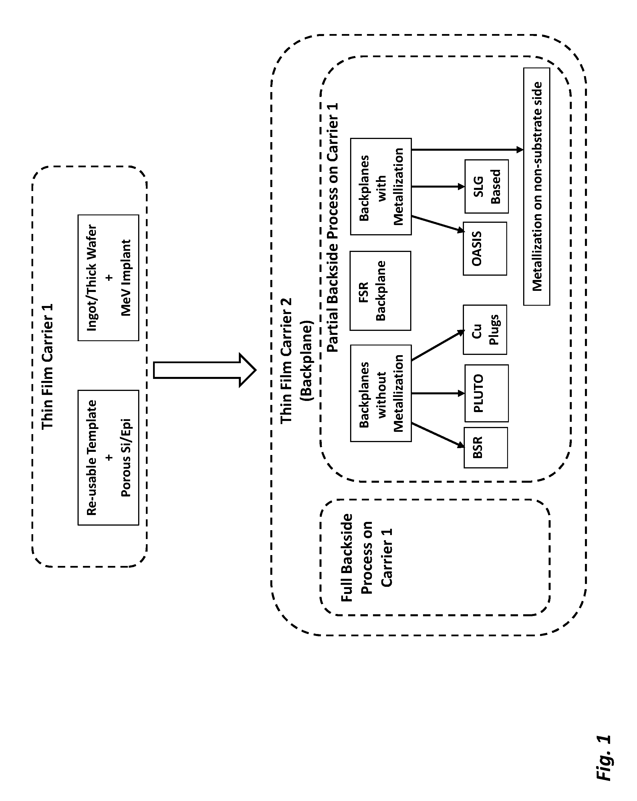
[0084]a permanent “Backplanes without Metallization” is a design known as acronym “PLUTO.” In this process flow, a simple and cheap backplane material (e.g., a relatively low-CTE Pre-preg material comprising a mixture of resin and fibers) is attached to the TFSS, while it is attached to the first carrier. The backplane attachment may be a direct bonding / lamination (if material has adhesive in it) or use an intermediate adhesive layer, for example a dielectric adhesive (DA) which may be printed using means such as screen printing (or applied using a spray coater or a roller coater). The pre-preg assembly / material choices should be such that they meet the following criteria:[0085]a. The released TFSS / Pre-preg assembly should be relatively stress and crack-free with very little bow.[0086]b. The backplane should maintain crack-free properties and should not induce stress cracks in the TFSS, while going through subsequent processing steps such as frontside texturing (e.g., using hot KOH)...
third embodiment
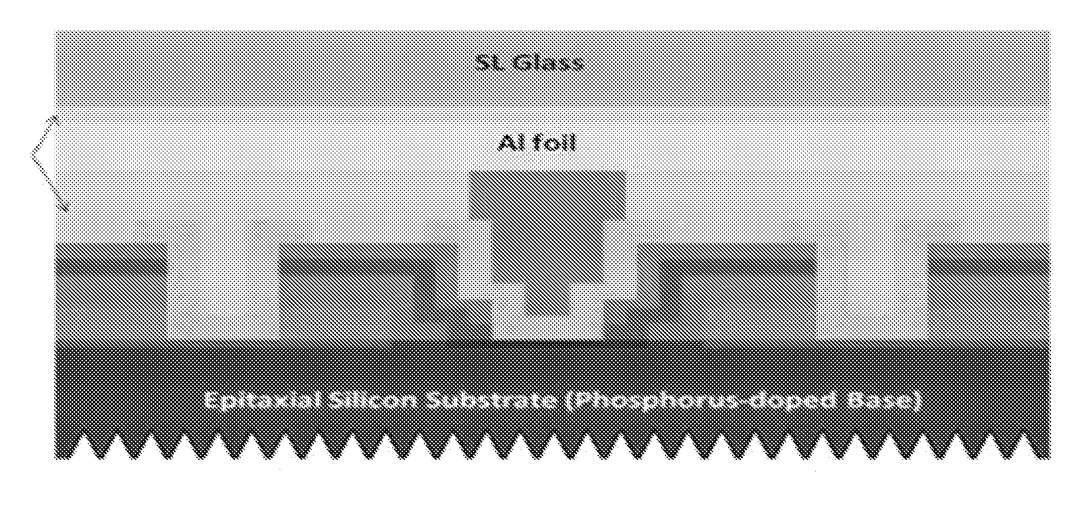
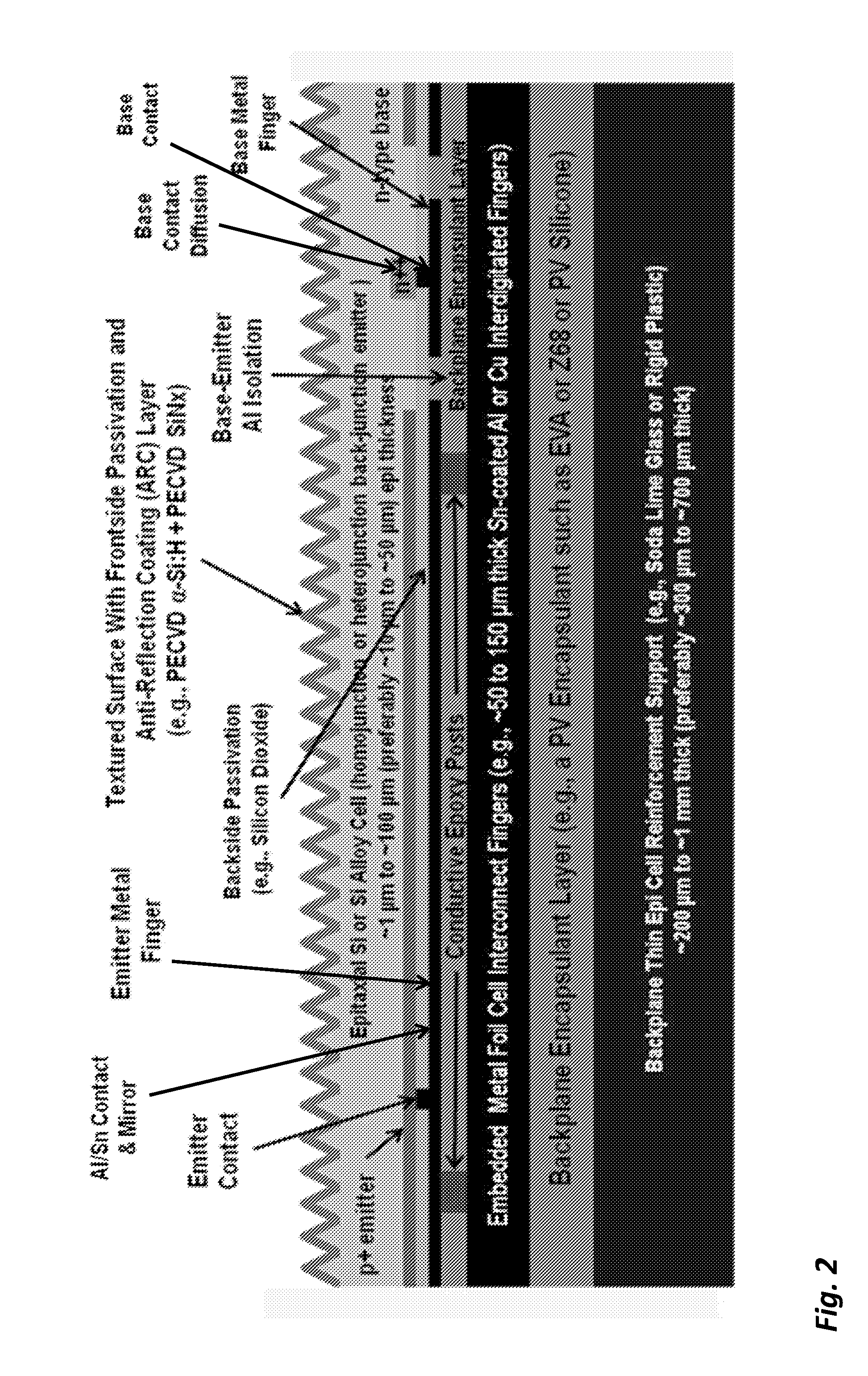
[0089]The third embodiment, “Cu Plugs,” of a permanent “Backplanes without Metallization” of FIG. 1 is a design with a slight modification of the aforementioned so-called PLUTO embodiment. And although, specifically identified with a metal as a naming convention, this approach should not be construed to be limited to copper as the electrically conductive material. In this case, the backplane has an additional layer backing compared to PLUTO. For example, the backplane may consists of glass or other harder solid backsheet materials (e.g., anodized Al) with a pliant attachment material such as an encapsulant PV-FS Z68 (from DNP Solar), also called Z68 in short, or Ethylene Vinyl Acetate (EVA). The backsheet may have pre-drilled holes, but the underlying attachment material serves as a sealant to protect the TFSS metal from being chemically attacked during frontside processing (such as during frontside wet alkaline texturing). After texture and passivation processes, the sealant materi...
first embodiment
[0159]FIG. 19, a hot ablation direct writing process, depicts a minimum steps process flow with the following noted attributes: two APCVD process steps used, has a texturing process, uses PSG and hot ablation to form base diffusion, selective emitter formed using laser, has a direct metal write process such as screen print, inkjet, aerosol print, laser transfer print, and direct solder bonding without CE screen print.
[0160]FIG. 20, a cold ablation direct writing process, depicts a second embodiment of the minimum process flow. It retains the common attributes of FIG. 19 of solder attachment as well as direct metal write to eliminate a few process steps. However, it differs from the FIG. 19 flow in that it does not rely on hot ablation and has three APCVD steps.
[0161]Non Epi Bulk Thin Substrate Process Flows.
[0162]Previously, two types of carrier 1 examples were disclosed. The first type of carrier 1 uses a template and the second type of carrier 1 is a thicker wafer or ingot from wh...
PUM
 Abstract
Description
Claims
Application Information
 - R&D
- Intellectual Property
- Life Sciences
- Materials
- Tech Scout
- Unparalleled Data Quality
- Higher Quality Content
- 60% Fewer Hallucinations
Browse by: Latest US Patents, China's latest patents, Technical Efficacy Thesaurus, Application Domain, Technology Topic, Popular Technical Reports.
© 2025 PatSnap. All rights reserved.Legal|Privacy policy|Modern Slavery Act Transparency Statement|Sitemap|About US| Contact US: help@patsnap.com


