Electric brake system for vehicles

a technology for electric brakes and vehicles, applied in the direction of braking systems, vehicle components, foot actuation initiations, etc., can solve the problems of inconvenient braking, no braking feel, and disadvantageous structure, and achieve accurate pressure control, simple configuration, and stable pedal feel during braking

Active Publication Date: 2013-08-22
HL MANDO CORP
View PDF6 Cites 27 Cited by
  • Summary
  • Abstract
  • Description
  • Claims
  • Application Information

AI Technical Summary

Benefits of technology

[0011]Therefore, it is one aspect of the present invention to provide an electric brake system for vehicles ...

Problems solved by technology

According to the patent document, the brake system fills a high-pressure and/or low-pressure accumulator with a hydraulic pressure by operating a motor and a pump, and increases, decreases, maintains or controls the hydraulic pressure by opening and closing an electronic solenoid valve, thus disadvantageously having a complicated structure.
In addition, since a predetermined gap is ...

Method used


Image

  • Electric brake system for vehicles
  • Electric brake system for vehicles
  • Electric brake system for vehicles

Examples


Embodiment Construction

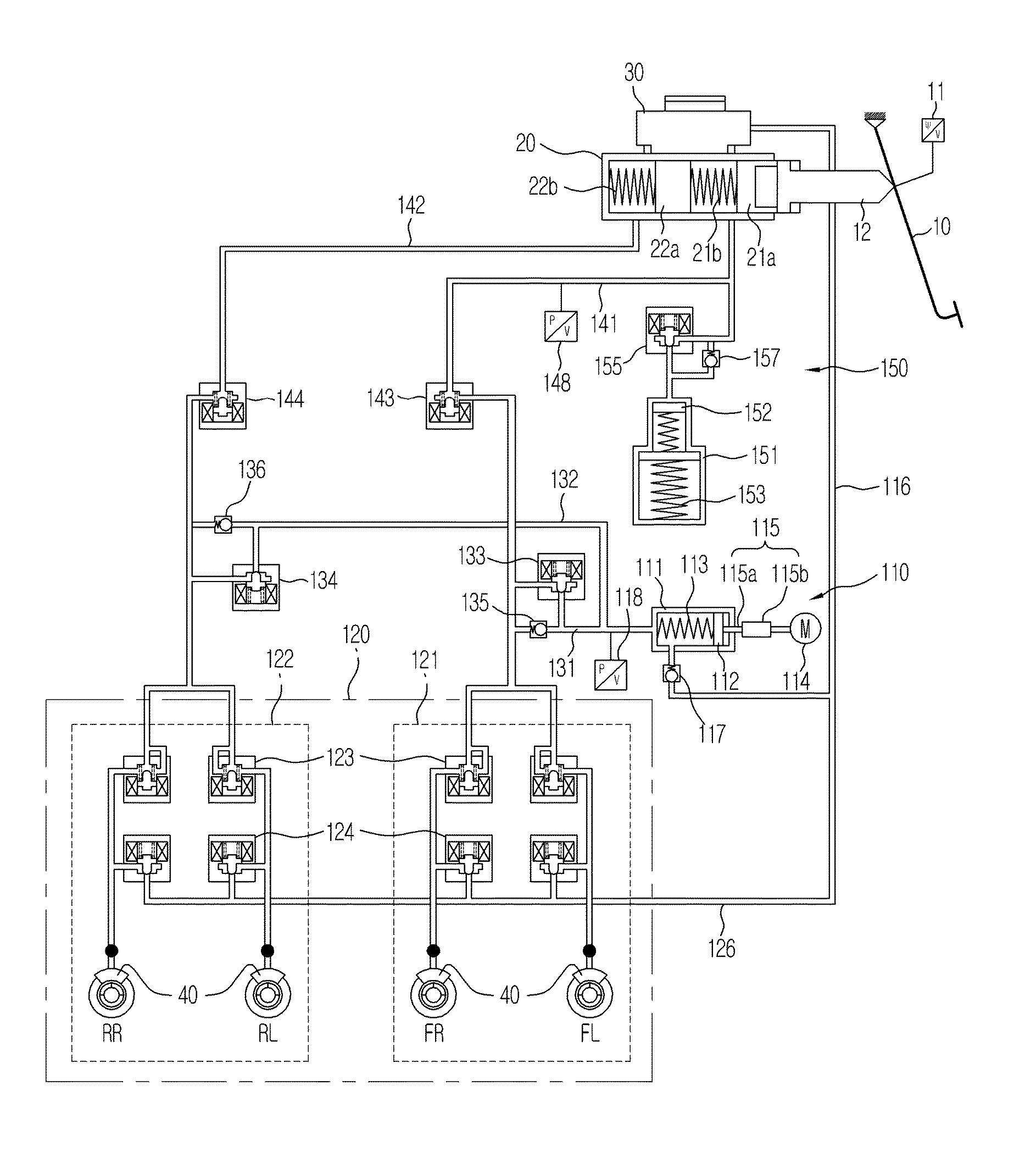
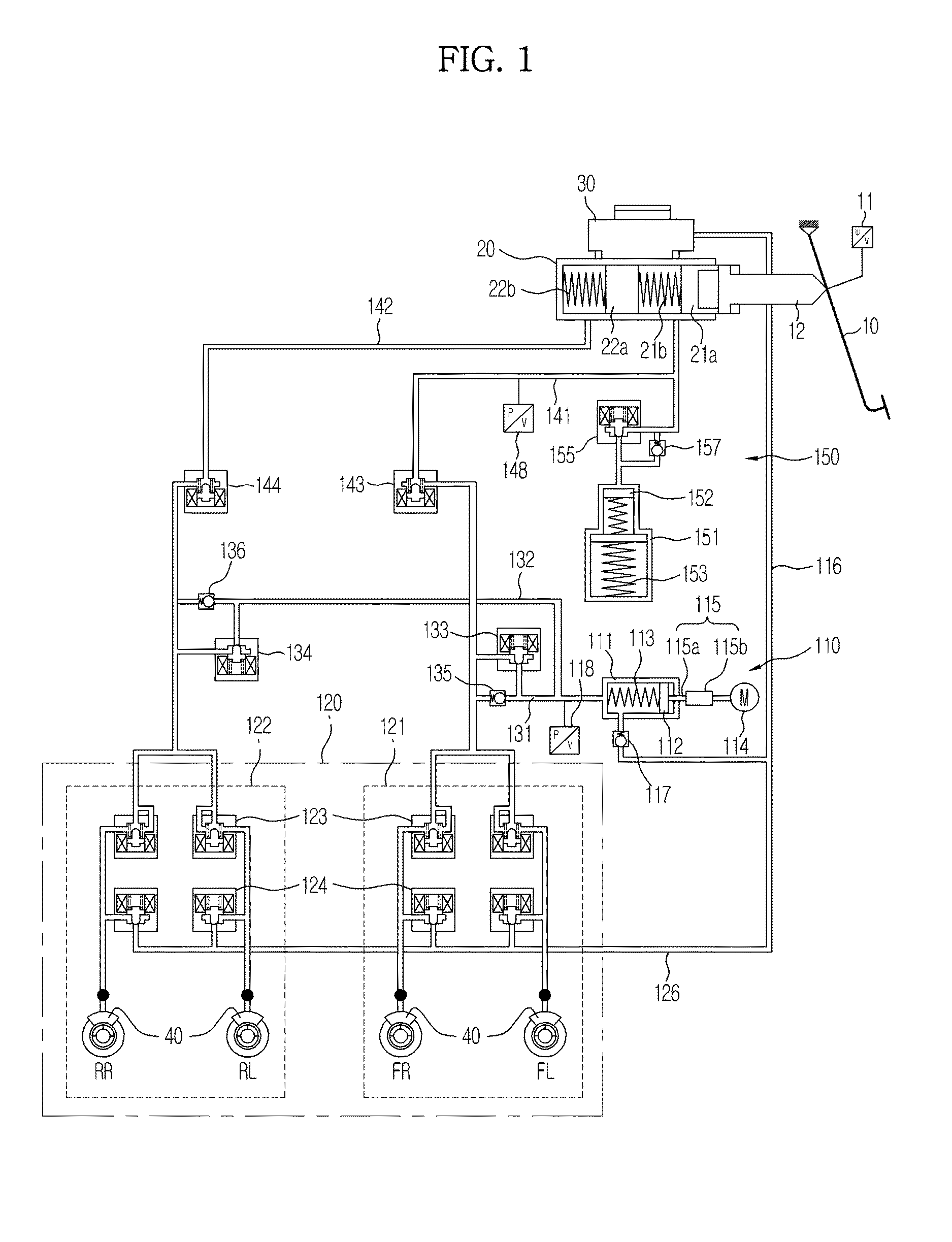
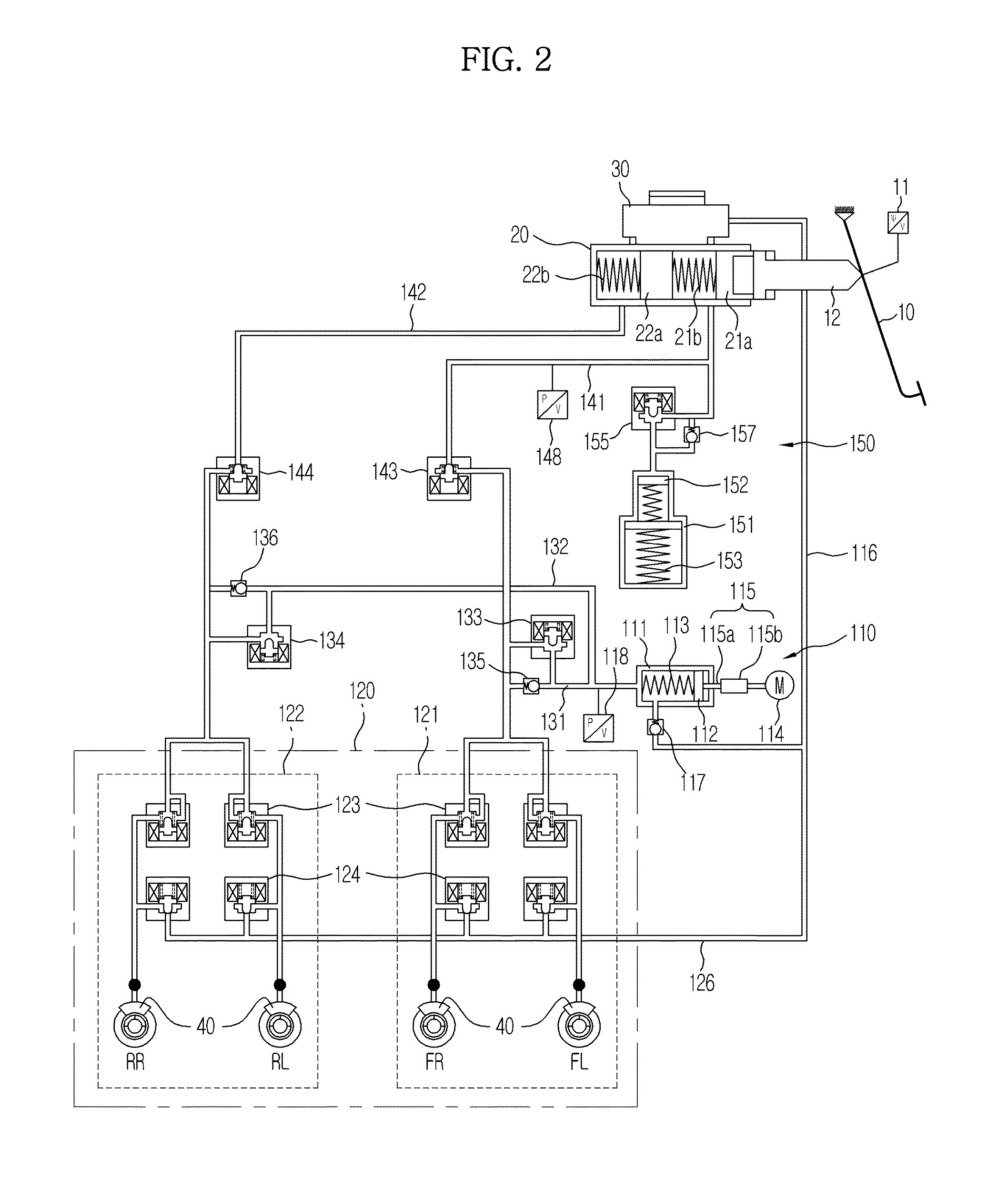
[0030]Reference will now be made in detail to the embodiments of the present invention, examples of which are illustrated in the accompanying drawings, wherein like reference numerals refer to like elements throughout.

[0031]The terms and words used in the present specification and claims should not be interpreted as being limited to typical meanings or dictionary definitions, but should be interpreted as having meanings and concepts relevant to the technical scope of the present invention based on the rule that an inventor can appropriately define the concepts of the terms to most appropriately describe the best method the inventor knows for carrying out the invention. Therefore, the configurations described in the embodiments and drawings of the present invention are merely most preferable embodiments but do not represent all of the technical spirit of the present invention. Thus, the present invention should be construed as including all the modifications, equivalents, and substit...


PUM


Abstract

The electric brake system for vehicles includes a pressure supplier connected to a reservoir through a hydraulic passage to receive the oil, the pressure supplier outputting a brake will of a driver as an electric signal through the pedal displacement sensor, when the driver puts the brake pedal, to operate a motor and convert a rotational force of the motor into linear motion, a hydraulic control unit including a first circuit including at least one first vehicle wheel and a second circuit including at least one second vehicle wheel to receive a hydraulic pressure with a force generated by the pressure supplier and thereby perform braking, a blocking valve to control the hydraulic pressure from the master cylinder to a wheel cylinder disposed in each vehicle wheel, a simulation device connected to the master cylinder, to provide a reaction force response to the pedal effort of the brake pedal, and an electronic control unit to control the motor and the valves, based on pressure information and pedal displacement information.

Description

CROSS-REFERENCE TO RELATED APPLICATION(S)[0001]This application claims the benefit of Korean Patent Application No. 2012-0013501, filed on Feb. 10, 2012 in the Korean Intellectual Property Office, the disclosure of which is incorporated herein by reference.BACKGROUND[0002]1. Field[0003]Embodiments of the present invention relate to an electric brake system for vehicles having a simple configuration, providing a stable pedal feel during braking and enabling accurate pressure control.[0004]2. Description of the Related Art[0005]Brake systems are necessarily mounted in vehicles. In recent years, a variety of systems to obtain stronger and more stable braking force have been suggested. Examples of brake systems include anti-lock brake systems (ABSs) to prevent slippage of wheels during braking, brake traction control systems (BTCSs) to prevent slippage of driving wheels during sudden acceleration of vehicles, and vehicle dynamic control systems (VDCs) to stably maintain a driving state ...

Claims


Application Information

Patent Timeline
IPC IPC(8): B60T13/68B60T7/06B60T13/74
CPCB60T13/686B60T13/745B60T8/4081B60T8/4018B60T7/06B60T13/12
Inventor YANG, I JIN
Owner HL MANDO CORP
Why Eureka
Try Eureka