
Low-noise, high bandwidth quasi-resonant mode switching power supply

a high-bandwidth, quasi-resonant technology, applied in the direction of electric variable regulation, process and machine control, instruments, etc., can solve the problems of spurious transmission or desensitization of receivers, noise types that can disrupt systems, and generate noise into radio bands, so as to improve the feedback control of switching power supply

Active Publication Date: 2013-08-22
QUANTANCE
View PDF3 Cites 18 Cited by
  • Summary
  • Abstract
  • Description
  • Claims
  • Application Information

AI Technical Summary

Benefits of technology

The patent text describes a combining network that uses a driver feedback loop to control the power supply. This loop includes a capacitor that helps to improve the feedback control of the power supply. The technical effect of this capacitor is to provide a more accurate measure of the current in the driver's output, which in turn helps to regulate the power supply in a more efficient and effective way.

Problems solved by technology

This type of noise can be disruptive to systems that amplify low level signals, for example, where the switching noise can couple into the circuitry and become amplified along with the desired signal.
Harmonics of the switching frequency, in particular can generate noise into radio bands and produce spurious transmissions or desensitize receivers.
Unfortunately, filtering also limits the responsiveness of the switching regulator to abrupt changes in load, line, or voltage setting.
Since the filters exhibit delay, it is generally not possible to include these filters inside the switching regulator's control loop for stability reasons.
Thus, low noise and responsiveness are frequently tradeoffs against one another.
However, higher switching frequencies result in higher magnetics losses and higher switching losses, decreasing power conversion efficiency.

Method used


Image

  • Low-noise, high bandwidth quasi-resonant mode switching power supply
  • Low-noise, high bandwidth quasi-resonant mode switching power supply
  • Low-noise, high bandwidth quasi-resonant mode switching power supply

Examples


Embodiment Construction

[0028]The figures and the following description relate to preferred embodiments of the present invention by way of illustration only. It should be noted that from the following discussion, alternative embodiments of the structures and methods disclosed herein will be readily recognized as viable alternatives that may be employed without departing from the principles of the claimed invention.

[0029]Reference will now be made in detail to several embodiments of the present invention(s), examples of which are illustrated in the accompanying figures. It is noted that wherever practicable similar or like reference numbers may be used in the figures and may indicate similar or like functionality. The figures depict embodiments of the present invention for purposes of illustration only. One skilled in the art will readily recognize from the following description that alternative embodiments of the structures and methods illustrated herein may be employed without departing from the principle...


PUM


Abstract

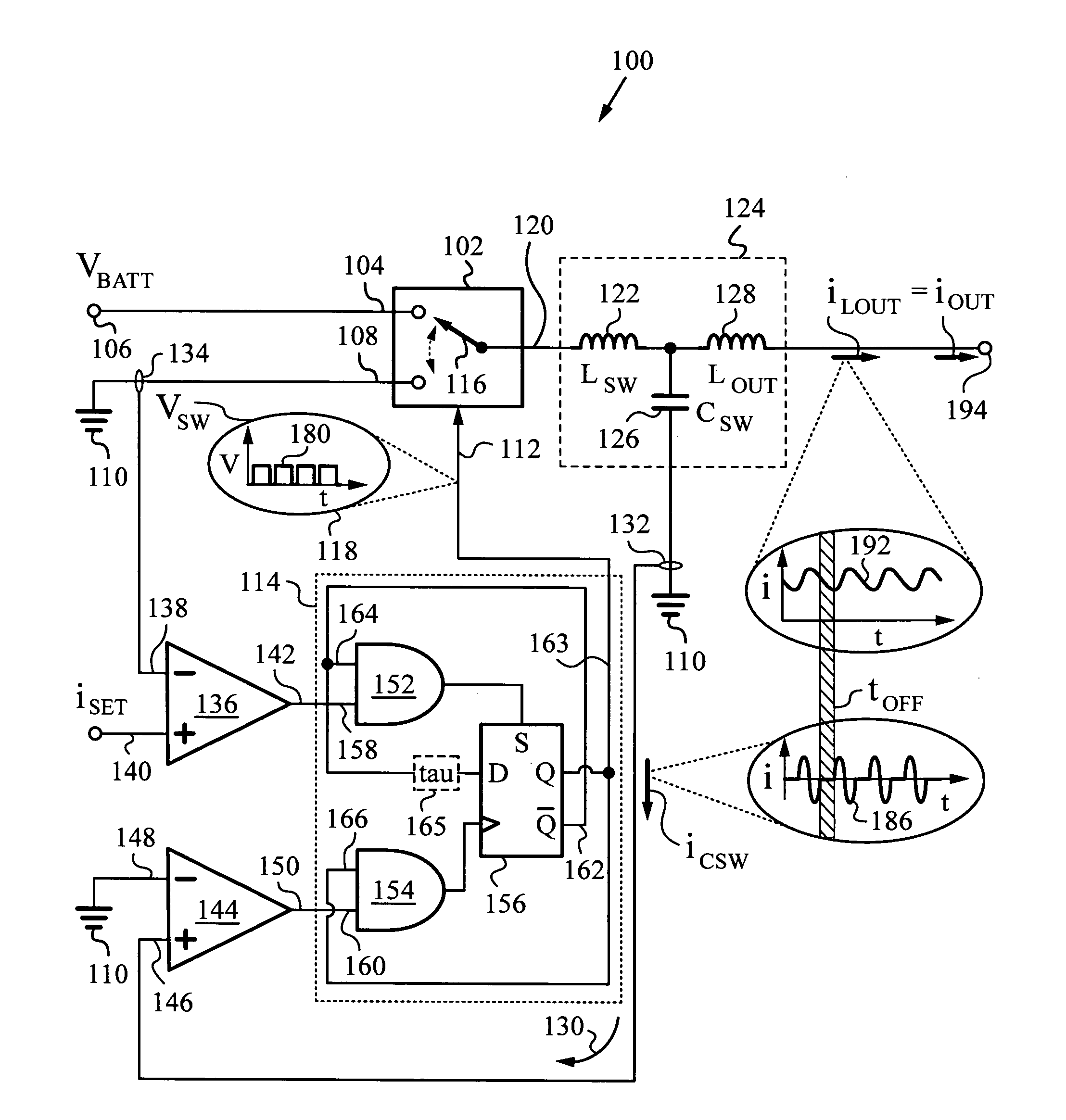
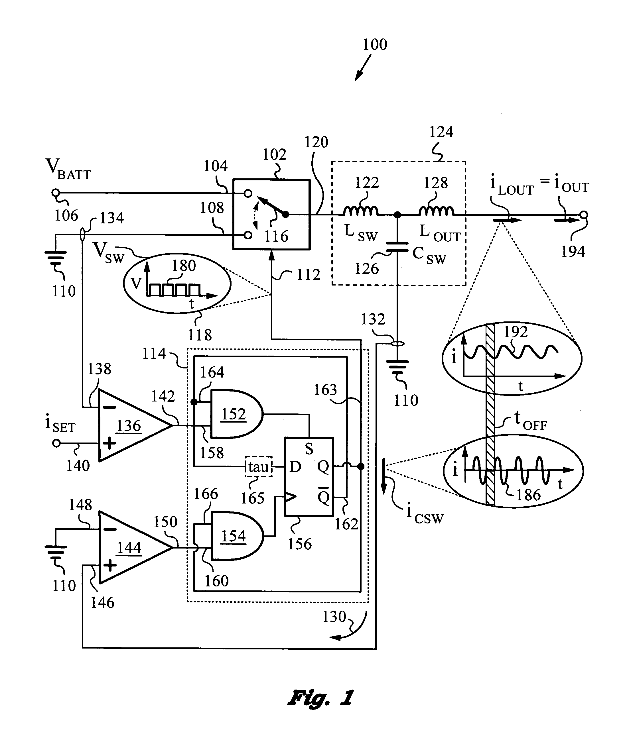
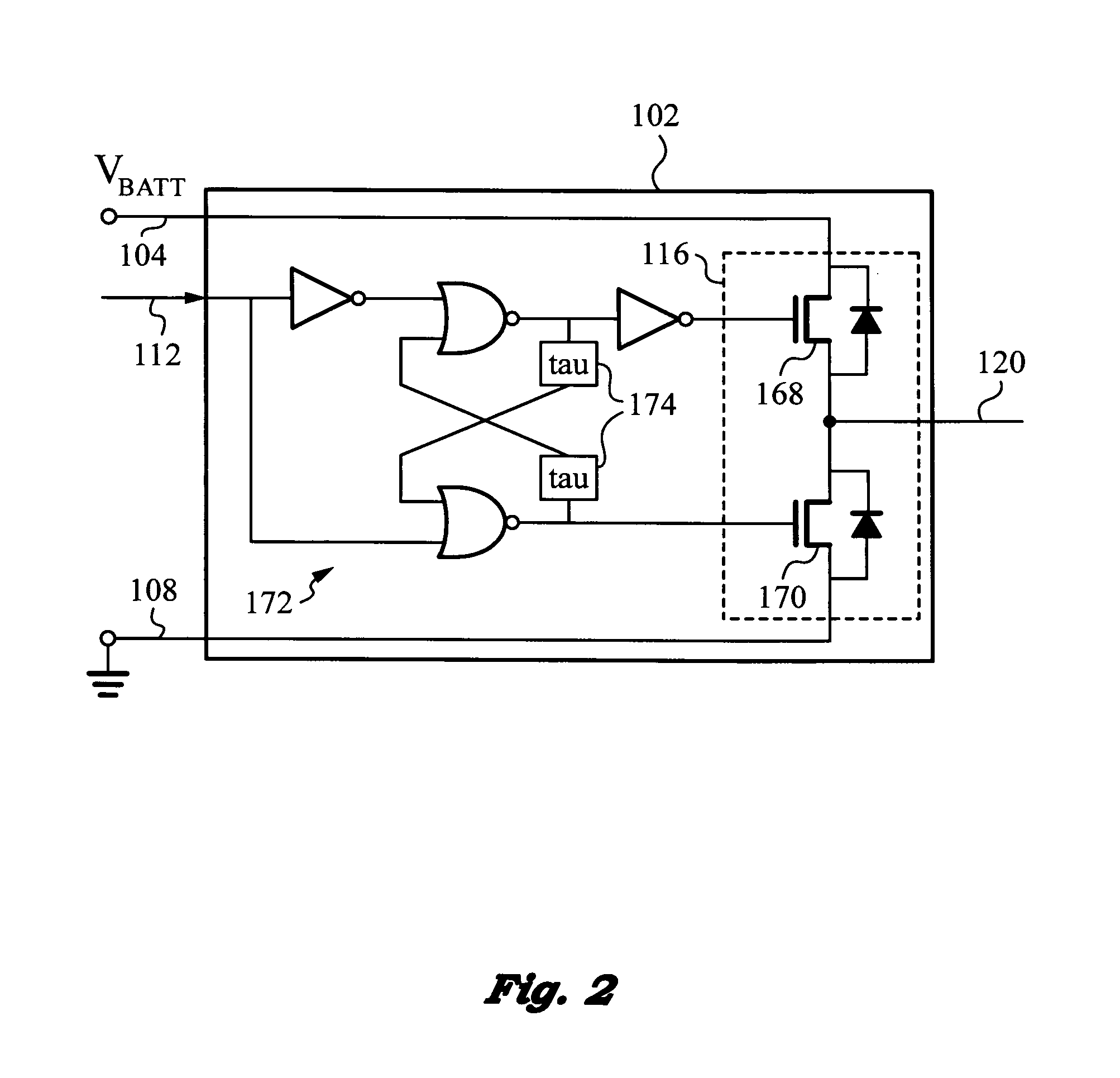
High bandwidth, low noise switching power supply operating in quasi-resonant mode for filtering switching harmonic noise, while providing a fast control bandwidth and power at high efficiency. The power supply has an LCL tank defining a resonance period Ttank, and a switching circuit regulation loop for turning on its switching circuit for on-time tON commencing at a time based on a state of regulation of the power supply. A switching capacitor current sensor triggers the switching circuit to turn off at the end of the resonance period Ttank, whereupon the switching and output inductors enter a discharging phase for a period not related to resonance period Ttank. “Quasi-resonant” operation, where the power supply is in resonant mode during on time tON and not in resonant mode during off time tOFF ensures that the output inductor filters the switching harmonic noise of the switching circuit.

Description

RELATED APPLICATIONS[0001]This application is related to U.S. application entitled “Dynamic Power Supply Employing a Linear Driver and a Switching Regulator” filed on the same date.FIELD OF THE INVENTION[0002]This invention relates generally to power supplies deploying switching regulators with high bandwidth and low noise, and more particularly to switching power supplies that filter switching harmonic noise.BACKGROUND ART[0003]Many electronic devices tend to require a highly responsive, low noise, high efficiency switching regulator.[0004]Switching regulators emit output current ripple at their switching frequency. That current is converted to switching voltage noise when driving a resistive load. This type of noise can be disruptive to systems that amplify low level signals, for example, where the switching noise can couple into the circuitry and become amplified along with the desired signal. Harmonics of the switching frequency, in particular can generate noise into radio bands...

Claims


Application Information

Patent Timeline
IPC IPC(8): G05F1/10
CPCH02M3/156H02M1/44Y02B70/1491Y02B70/1425H02M2001/0058H02M1/0058Y02B70/10
Inventor TOURNATORY, DAVID C.G.
Owner QUANTANCE
Learn More