
Apparatus, method and system for managing data transmission

a technology of data transmission and apparatus, applied in the field of communication systems, can solve the problems of reducing inefficient use, and inefficient transmission of data as soon as it is available to be transmitted, so as to reduce the ability of other devices, reduce the overall system efficiency, and reduce the length of time

Inactive Publication Date: 2013-08-22
IPLA HLDG
View PDF6 Cites 28 Cited by
  • Summary
  • Abstract
  • Description
  • Claims
  • Application Information

AI Technical Summary

Benefits of technology

This patent proposes a solution to improve the efficiency of transmitting data in communication systems, especially in wireless data transmission systems. The solution involves storing data in a buffer and transmitting it when the data reaches a certain threshold. This reduces the need for frequent exchange of signs between the transmitting device and the network, resulting in improved network resource utilization and reduced power consumption. The patent also provides a way to accommodate different degrees of delay tolerance in data streams by adjusting the data threshold accordingly.

Problems solved by technology

In some communication systems transmitting data as soon as it is available to be transmitted can be very inefficient, for example when data is intermittently transmitted in bursts of low quantities of data.
In systems such as wireless data transmission systems this may be an inefficient use of valuable network resources as signalling information must be exchanged between the data transmitting device and the receiver before each small burst of data is transmitted.
The exchange of the signalling information to transmit the small amount of data reduces the ability for other devices in the system to access the network resources, therefore reducing overall system efficiency.
Moreover, the frequent exchange of signalling information with the network can be very power consuming, thus reducing the length of time during which an internal power source in the transmitting device such as a battery can provide power, for example.

Method used


Image

  • Apparatus, method and system for managing data transmission
  • Apparatus, method and system for managing data transmission
  • Apparatus, method and system for managing data transmission

Examples


Embodiment Construction

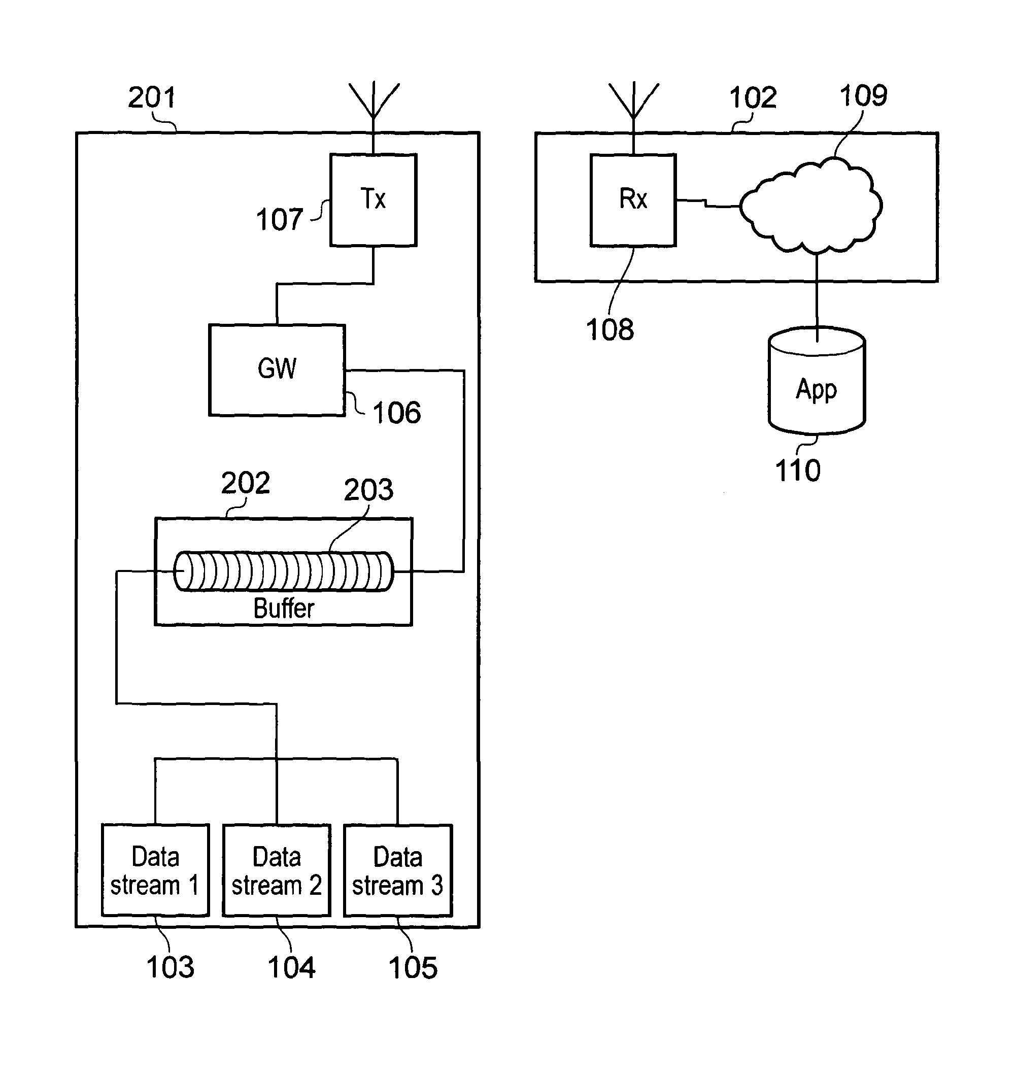
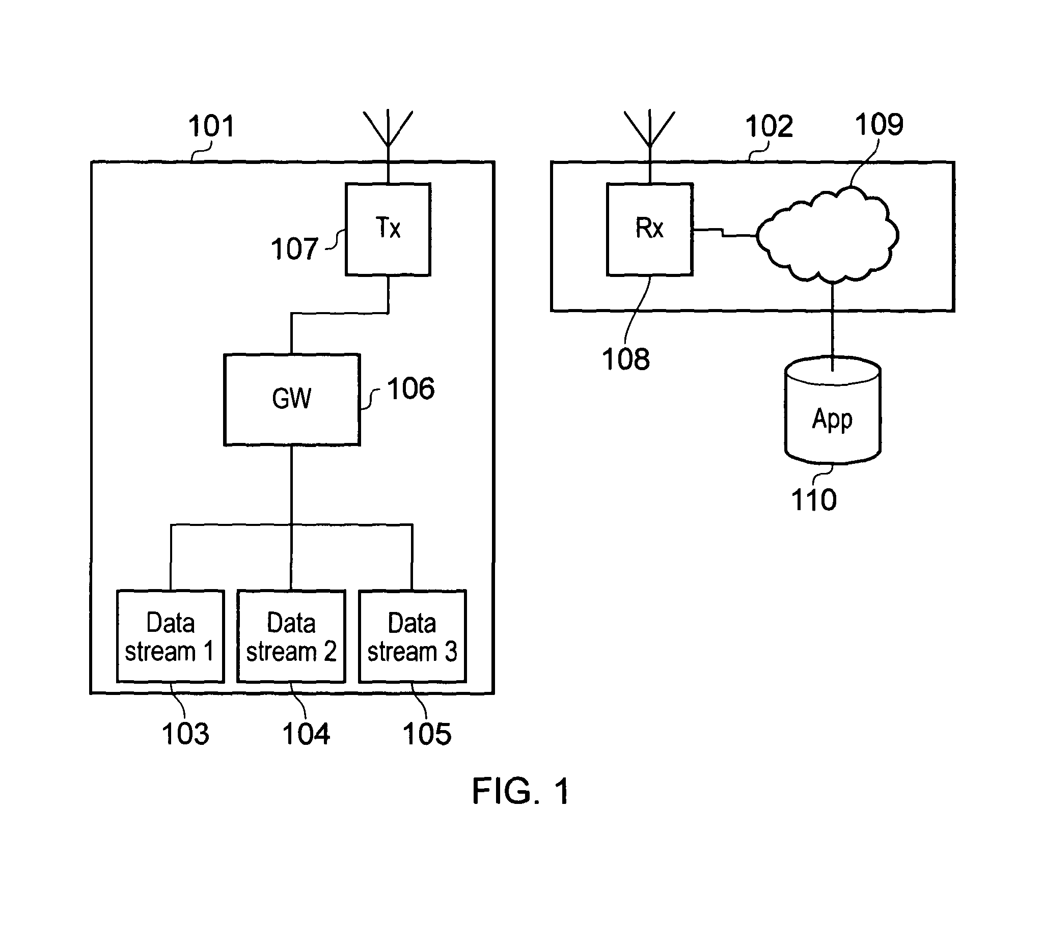
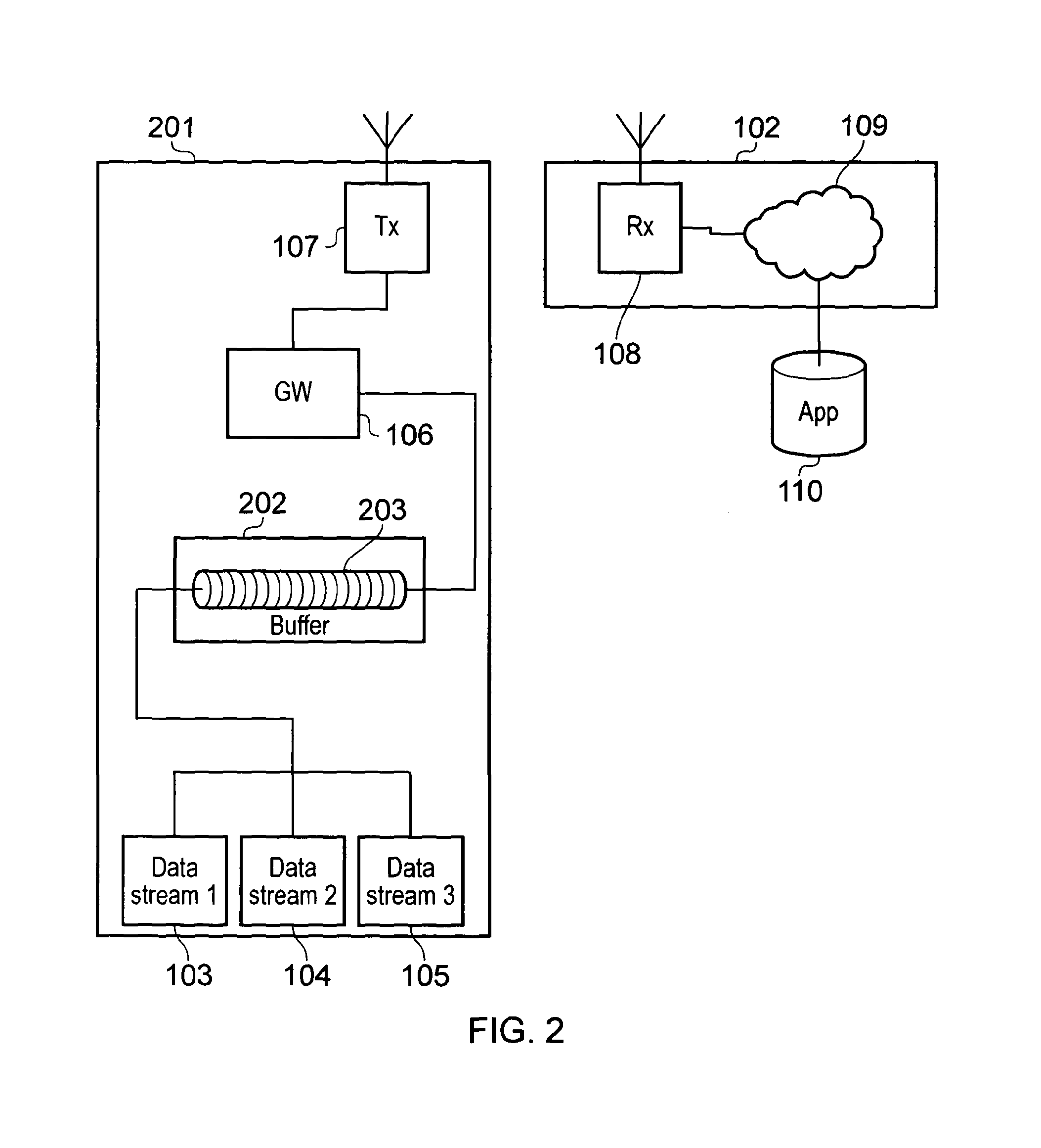
[0032]FIG. 1 shows a schematic diagram illustrating an example of a conventional wireless communication system. The communication system includes a transmitter unit 101 which is arranged to communicate data to a network 102. The transmitter unit 101 includes a first data stream 103, a second data stream 104 and a third data stream 105. The data streams send data to a data gateway 106. The data gateway 106 converts the data received from the data streams 103, 104, 105 into a format suitable for wireless transmission and sends the data to a transmitter 107 which wirelessly transmits the data to a receiver 108 in the network 102 via a wireless interface. The received data is sent via network routing 109 to an application server 110 which processes the received data as required. The data streams may each originate from different devices such as a sensor providing various telemetry information to the application server 110.

[0033]The wireless interface may be provided using conventional c...


PUM


Abstract

An apparatus for managing data transmission in a telecommunications system, including a buffer unit arranged to receive data from one or more sources of data and to forward the data to a transmitter for transmission. The buffer unit is configured to delay the transmission of the data by storing the data for a time before forwarding it to the transmitter. The buffer unit is also configured to forward the stored data to the transmitter for transmission when an amount of data stored in the buffer unit reaches a predefined threshold.

Description

BACKGROUND[0001]The present invention relates to communication systems and more particularly to methods and apparatus for managing data transmission in communications system.[0002]Communication systems, particularly wireless telecommunication systems, that allow data to be transmitted from a transmitter to a receiver in a network are well known and commonly used. Examples include systems arranged in accordance with the IEEE 802.11 set of standards (sometimes referred to as “WiFi”) and mobile communication networks arranged in accordance with the 3GPP standards, 3GPP systems include communication systems using the General Packet Radio System (GPRS), UMTS systems employing the Enhanced Uplink (EUL) (sometimes referred to as High Speed Uplink Packet Access (HSUPA)) and systems arranged in accordance with the more recently defined Long Term Evolution (LTE) standard.[0003]Whilst these communication systems typically provide high data rates over robust radio links, at present they are not...

Claims


Application Information

Patent Timeline
IPC IPC(8): H04W4/00H04W4/70
CPCH04W52/0261H04W4/005H04W72/1242H04W72/1221H04W4/70Y02D30/70H04W72/569G08C17/02H04L25/05H04L49/90
Inventor ZAKRZEWSKI, ROBERT
Owner IPLA HLDG
Learn More