Fuel cell system

a fuel cell and system technology, applied in the field of fuel cell systems, can solve the problems of insufficient response not necessarily obtained in a system, performance of the evaporator, and the inability to stop the evaporation of liquid fuel in the evaporator immediately, so as to reduce the efficiency of the system, reduce the performance of the evaporator, and increase the load fluctuation

Inactive Publication Date: 2006-09-19
NISSAN MOTOR CO LTD
View PDF18 Cites 2 Cited by
  • Summary
  • Abstract
  • Description
  • Claims
  • Application Information

AI Technical Summary

Benefits of technology

[0004]However, when fuel is vaporized in the evaporator and fuel gas is supplied to the reformer in this way, a sufficient response is not necessarily obtained in a system where the fuel cell has a large load fluctuation such as an automobile. Moreover, when the system is stopped, evaporation of the liquid fuel in the evaporator cannot be stopped immediately. Further, caulking (plugging of the evaporator) easily occurs due to the fuel remaining within the evaporator, degrades the performance of the evaporator, and causes the efficiency of the system to decline.

Problems solved by technology

However, when fuel is vaporized in the evaporator and fuel gas is supplied to the reformer in this way, a sufficient response is not necessarily obtained in a system where the fuel cell has a large load fluctuation such as an automobile.
Moreover, when the system is stopped, evaporation of the liquid fuel in the evaporator cannot be stopped immediately.
Further, caulking (plugging of the evaporator) easily occurs due to the fuel remaining within the evaporator, degrades the performance of the evaporator, and causes the efficiency of the system to decline.

Method used


Image

  • Fuel cell system
  • Fuel cell system
  • Fuel cell system

Examples


second embodiment

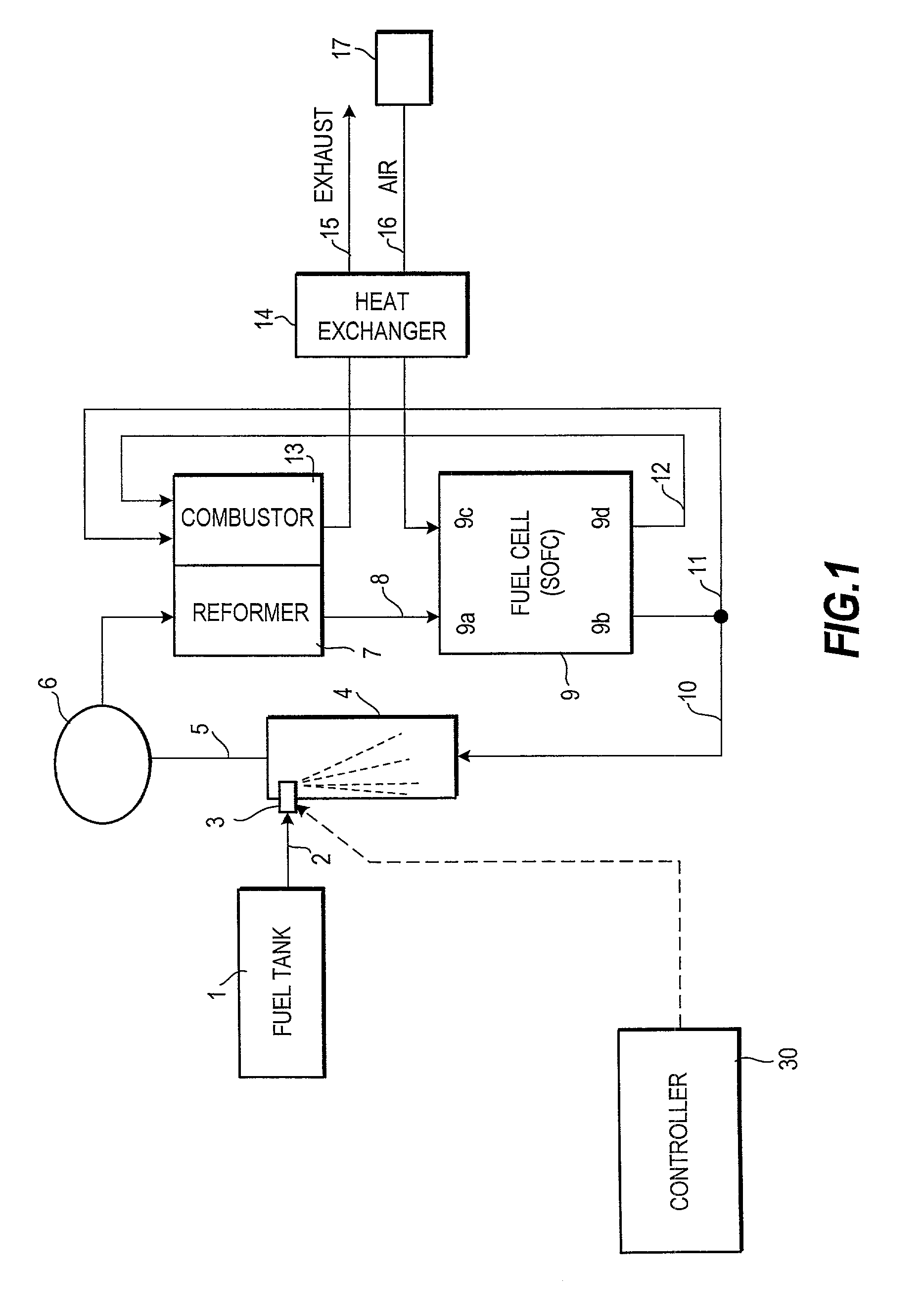
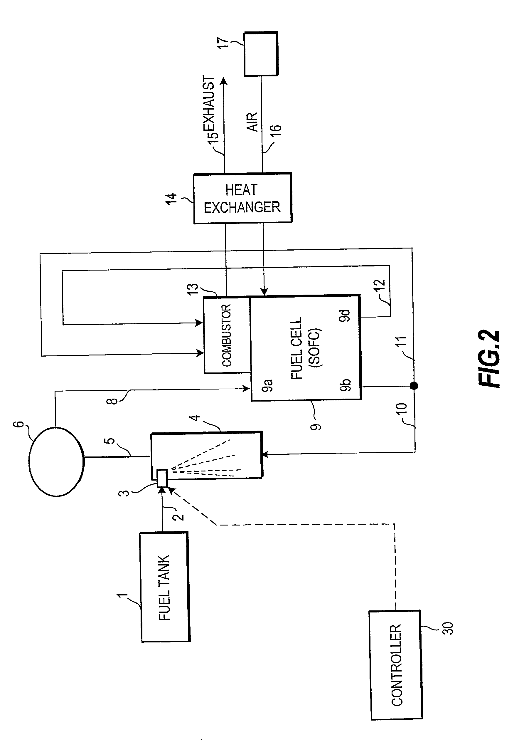
[0025]FIG. 2 shows this invention.

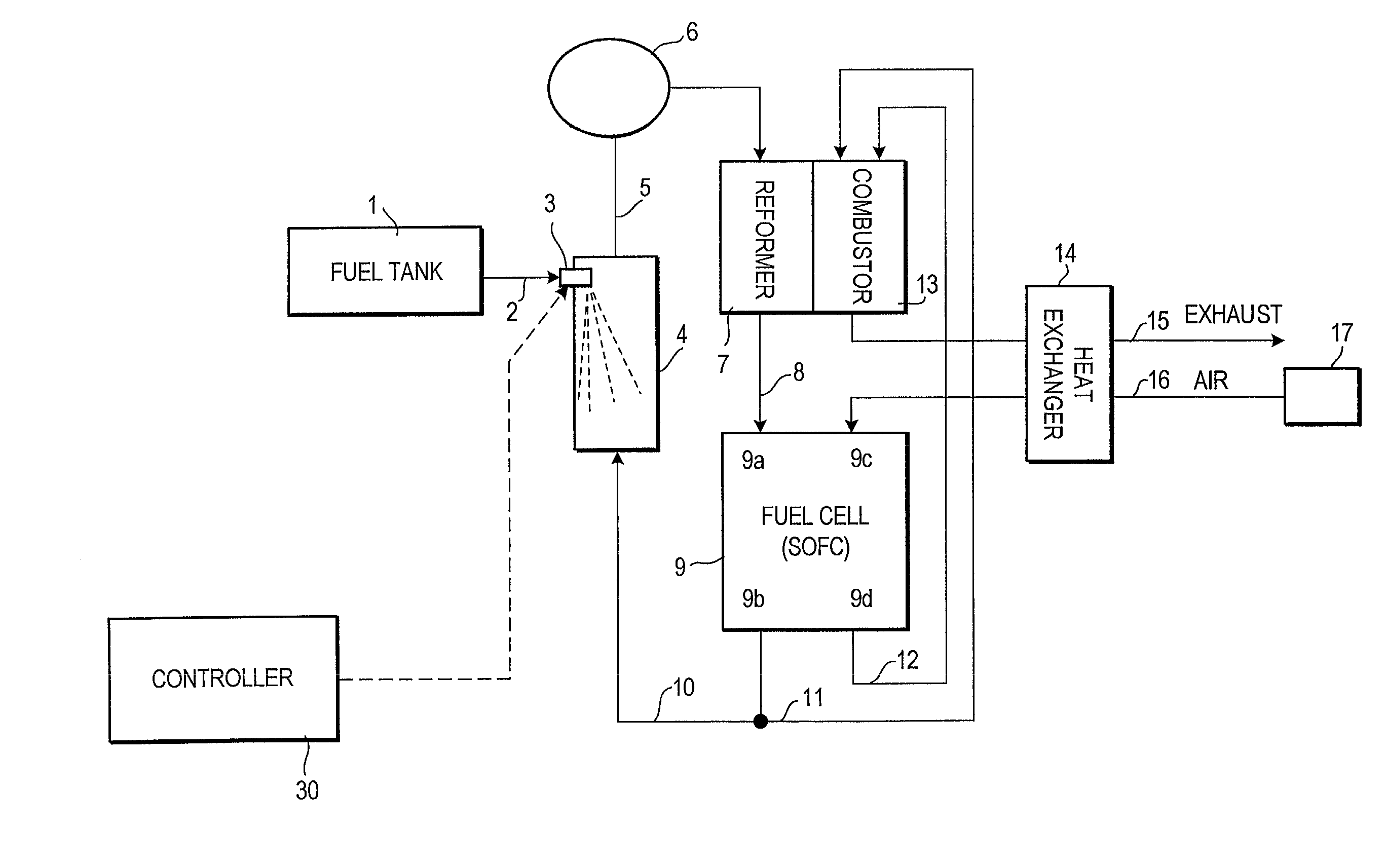
[0026]In this embodiment, the fuel stored in the fuel tank 1 in the liquid state is supplied to the fuel cell 9 by spraying from the injector 3 and mixing with the circulated anode exhaust gas which is part of the anode exhaust gas from the anode outlet 9b as in the first embodiment.

[0027]In this embodiment, the fuel cell 9 is an internal reforming type wherein fuel reforming is performed inside the fuel cell 9, and the circulated exhaust gas and fuel gas which were mixed in the vaporizer 4 are directly supplied to the fuel cell fuel gas inlet port 9a via the circulation blower 6. Although the heat of the fuel cell is taken up by the reforming reaction in the case of an internal reforming type fuel cell, the heat can be supplemented by the combustor 13 which burns the anode exhaust gas and cathode exhaust gas.

third embodiment

[0028]FIG. 3 shows this invention.

[0029]In this embodiment, in a fuel cell system identical to that of the first embodiment, a water feeder (water tank 20, water supply passage 21 and injector 22) is added to the vaporizer 4. Further, a steam amount (mol / sec) and fuel amount in the circulated anode exhaust gas supplied to the vaporizer 4 via the anode exhaust gas circulation passage 10 are detected respectively by a differential pressure type steam flowrate sensor 18 and fuel component sensor 19 comprising an optical humidity sensor.

[0030]Specifically, the water stored in the water tank 20 is supplied to the injector 22 via the water supply passage 21, and is injected into the vaporizer 4 from the injector 22.

[0031]Of the anode exhaust gas from the anode outlet 9b, anode exhaust gas circulated via the anode exhaust gas circulation passage 10 is supplied to the vaporizer 4, and the fuel injected from the injector 3, water injected from the injector 22 and circulated anode exhaust gas...


PUM

PropertyMeasurementUnit
temperatureaaaaaaaaaa
pressureaaaaaaaaaa

Abstract

A fuel cell system includes a fuel cell (9), an exhaust gas circulation passage (10) which circulates part of the exhaust gas from the fuel cell (9) back to the fuel cell (9), a fuel injector (3) which injects liquid fuel into the circulated exhaust gas, and a vaporizer (4) which vaporizes the injected fuel. The fuel cell system has a high response, as the liquid fuel injected into the exhaust gas rapidly vaporizes.

Description

FIELD OF THE INVENTION[0001]This invention relates to a fuel cell system wherein power is generated using the fuel gas generated from liquid fuel.BACKGROUND OF THE INVENTION[0002]JP-A-2000-100462 published by the Japanese Patent Office in 2000 discloses a technique wherein liquid fuel is sent to an evaporator according to the load of a fuel cell, and the liquid fuel is vaporized and supplied to a reformer. In the reformer, part or all of the hydrocarbon fuel is reformed into hydrogen according to the following equations (1) and (2).CnH2n+2+nH2O→nCO+(n+2)H2  (1)CO+H2O→CO2+H2  (2)[0003]The hydrogen obtained by reforming is supplied to the anode of a fuel cell.SUMMARY OF THE INVENTION[0004]However, when fuel is vaporized in the evaporator and fuel gas is supplied to the reformer in this way, a sufficient response is not necessarily obtained in a system where the fuel cell has a large load fluctuation such as an automobile. Moreover, when the system is stopped, evaporation of the liquid...

Claims


Application Information

Patent Timeline
Patent Type & Authority Patents(United States)
IPC IPC(8): H01M8/04H01M8/06H01M8/12
CPCH01M8/0612H01M8/0625H01M2250/20Y02E60/50H01M2300/0074Y02T90/32H01M2300/0051Y02T90/40
Inventor IWASAKI, YASUKAZUHARA, NAOKI
Owner NISSAN MOTOR CO LTD
Why Eureka
Try Eureka