Fuel accumulator block for testing high-pressure components of fuel injection systems

a fuel accumulator and high-pressure component technology, which is applied in the direction of fuel injection apparatus, machine/engine, feed system, etc., can solve the problems of o-ring seals other components, such as pressure sensors or pressure limiting valves, may fail prematurely, etc., to achieve the effect of increasing the service life of pressure control valves, reducing temperature stress, and improving service li

Active Publication Date: 2013-08-29
ROBERT BOSCH GMBH
View PDF11 Cites 12 Cited by
  • Summary
  • Abstract
  • Description
  • Claims
  • Application Information

AI Technical Summary

Benefits of technology

[0005]An example fuel accumulator block according to the present invention may have the advantage that, because of the cooling of the accumulator body, the temperature-critical places, particularly of the pressure control valves installed in the accumulator body, are exposed to a lower temperature stress, so that their service life is increased. Besides that, by cooling the accumulator body, it is possible further to raise the test pressure for the components without exceeding the admissible temperatures, without bringing on the destruction of the pressure control valves, for example. This means at the same time that the service life of the pressure control valves is increased even at test pressures above 200 MPa. In addition, the pressure load of the fuel accumulator block is increased by the cooling of the accumulator body. Because of the low temperature level of the fuel accumulator block, the operator of the testing device is also protected from possible injury. Furthermore, because of the low temperatures of the test oil, the measuring system is protected.

Problems solved by technology

However, the main quantity of the fuel flows through the fuel injectors.
Therefore, its flow through the pressure control valve is limited, so that in this instance explicit cooling becomes necessary.
Thus, for example, at pressures of 200 MPa and through-flows of more than 70 liter per hour, the admissible operating temperatures for the pressure control valves are exceeded, whereby in particular, the O-ring seals of the pressure control valves are endangered.
Other components, such as pressure sensors or pressure limiting valves, may fail prematurely because of the higher temperatures.
Besides, at increasing temperature, the stability of the fuel accumulator block (test rail) becomes decreased, particularly with respect to a high pressure load.

Method used


Image

  • Fuel accumulator block for testing high-pressure components of fuel injection systems
  • Fuel accumulator block for testing high-pressure components of fuel injection systems
  • Fuel accumulator block for testing high-pressure components of fuel injection systems

Examples


Embodiment Construction

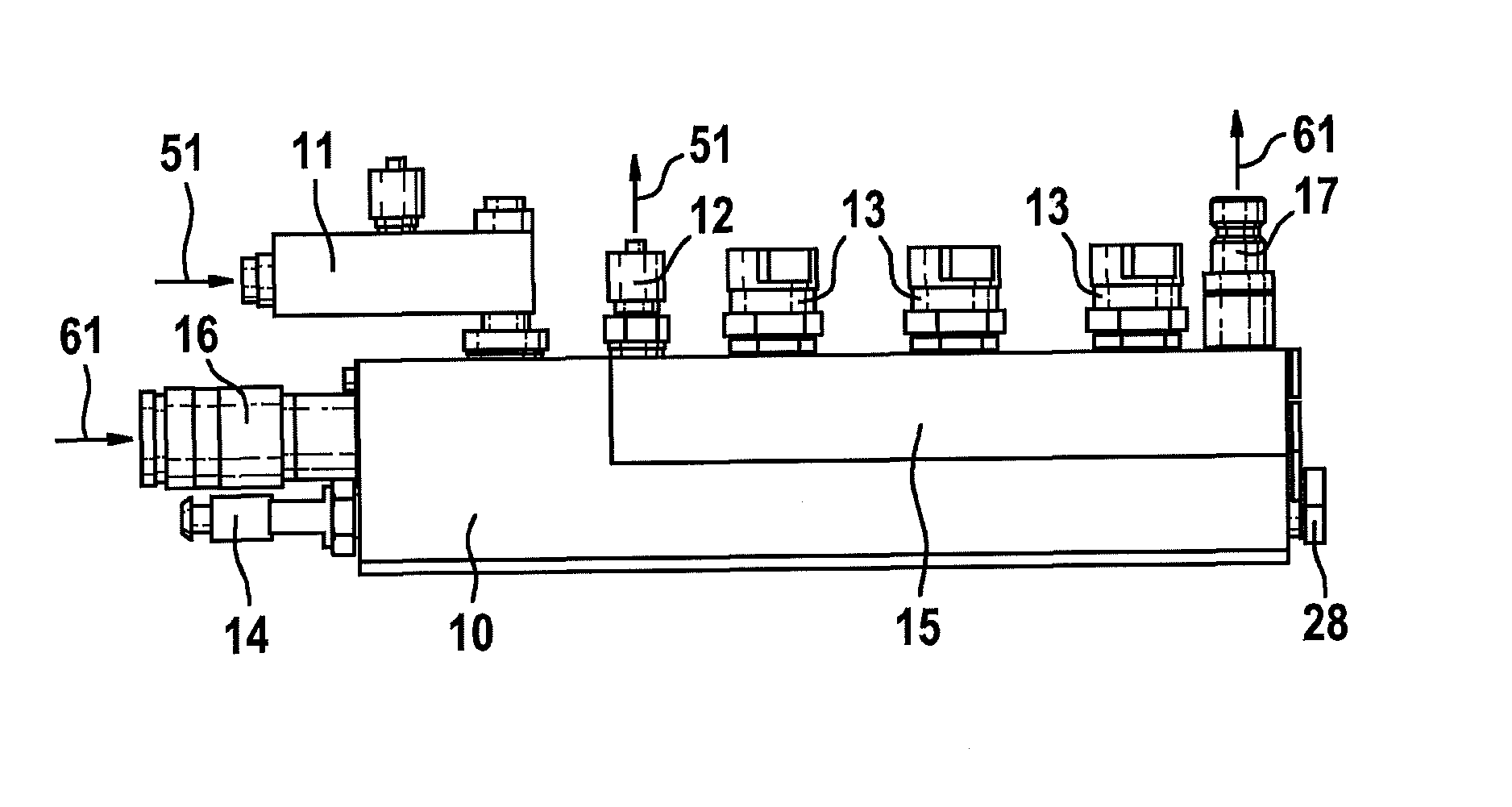
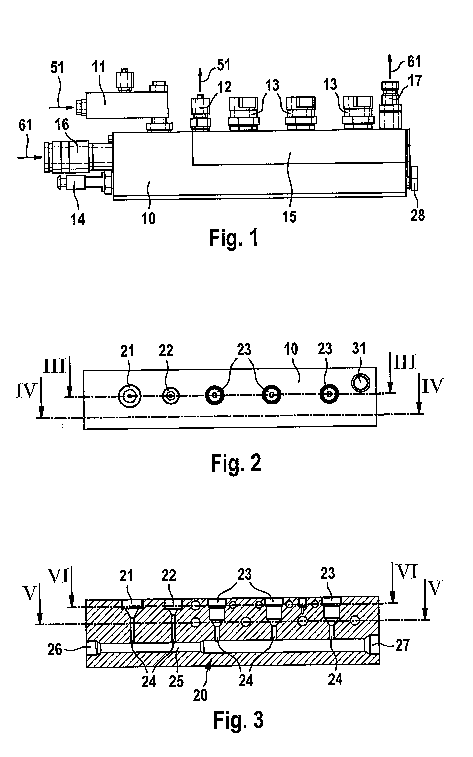
[0018]The fuel accumulator block shown in FIG. 1 includes an accumulator body 10 along with attachment components situated on it, such as an inlet connector 11 and an outlet connector 12 for connecting a test line 51, respectively shown schematically by arrows, for a test medium, such as test oil, an additional inlet connector 16 and an additional outlet connector 17 for connecting a cooling line 61 for circulating cooling medium, respectively shown schematically by arrows. Accumulator body 10 is used as a test rail, for example, for testing high-pressure components of fuel injection systems of motor vehicles, e.g. of high-pressure pumps or fuel injectors.

[0019]In accumulator body 10, furthermore, for instance, three pressure control valves 13 for controlling the test pressure as well as a pressure sensor 14 for recording the test pressure are used as attachment components. On accumulator body 10, furthermore, a test oil collector 15 is flange-mounted as an attachment component, int...


PUM


Abstract

A fuel accumulator block is provided for testing high-pressure components of fuel injection devices. The fuel accumulator block includes an accumulator body and at least one pressure control valve, which is accommodated in a receptacle in the accumulator body. The accumulator body is connected to a test line for a test medium and to a cooling line for a cooling medium. Within the accumulator body a test line run is developed for the test medium and a cooling line run is developed for the cooling medium. The cooling line run has at least one section which runs in the vicinity of the receptacle for the pressure control valve.

Description

FIELD[0001]The present invention relates to a fuel accumulator block according to the preamble of Claim 1.BACKGROUND INFORMATION[0002]In auto repair shops, for testing high-pressure components of fuel injection systems of motor vehicles, such as high-pressure pumps or fuel injectors, testing units are used which include a fuel accumulator block as a so-called test rail. The higher the test pressures rise in the testing of the high-pressure components, the higher are the temperatures that occur in the test rail. These temperatures are created both by the compression of the test medium (testing oil) of up to 250 MPa and by the friction taking place at the pressure control valves acting as throttles, as well as by heating by the electromagnetic switching valve of the pressure control valve. To cool pressure control valves in common rail installed in motor vehicles, the pressure control valve has fuel flowing around it, which thereby already generates cooling. However, the main quantity...

Claims


Application Information

Patent Timeline
Patent Type & Authority Applications(United States)
IPC IPC(8): F02M59/44
CPCF02M53/00F02M65/00F02M59/44F02M65/002F02M65/001
Inventor STEIN, RALFHOSS, REINHARD
Owner ROBERT BOSCH GMBH
Why Eureka
Try Eureka