Heat storage system

a technology of heat storage and heat exchanger, which is applied in the direction of solar heat storage, indirect heat exchangers, lighting and heating apparatus, etc., can solve the problems of large amount of sand traveling considerable distances, reducing the efficiency of solar power plants, corrosion and abrasion of various components, etc., and achieves the effects of increasing the energy yield of the system, saving energy consumption, and economical design

Active Publication Date: 2013-08-29
VIENNA UNIVERSITY OF TECHNOLOGY
View PDF8 Cites 10 Cited by
  • Summary
  • Abstract
  • Description
  • Claims
  • Application Information

AI Technical Summary

Benefits of technology

[0028]In a preferred embodiment, the inventive heat storage system includes a system for recovering heat from the fluidizing medium as an additional component, which further increases the energy yield of the system. This system may, for example, comprise recuperative gas heat exchangers above the fluidized bed heat exchanger. Also, fluidizing media from several chambers with similar temperature levels may be bundled and introduced into a common recuperative gas heat exchanger in order to allow an economical design and to recover heat from the fluidizing medium at the highest possible exergetic level.
[0029]According to a further preferred embodiment of the invention, heat loss through the fluidizing medium is minimized by providing means for collecting and recycling fluidizing medium above the fluidized bed heat exchanger. Thus, a hot fluidizing medium may—optionally together with a fresh, newly introduced medium—be repeatedly introduced into the fluidized bed heat exchanger in order to transfer as much of the heat amount contained therein as possible to the sand. Recirculation may, for example, be achieved by means of one or more fluidizing blowers running in a hot mode.
[0030]In a further, particularly preferred embodiment, means for redirecting the sand in a horizontal direction are provided in one or more chambers of the heat exchanger of the invention. They control the movement of the sand fluidized bed through the respective chamber and may, for example, urge the sand preferably to one side of the chamber and / or cause the sand to move through the chamber in serpentines or meanders. This allows, on the one hand, control of the dwell time of the sand in the chamber, and on the other hand the adjustment of the direction of its movement through the respective chamber to the course of the ducts for heat transfer. For the latter purpose, the redirection means are preferably selected and arranged to achieve a countercurrent between the sand and the medium carried in the ducts within the chamber, which further improves the heat exchange. In addition or alternatively, the course of the ducts may be selected to optimally adapt it to the direction of movement of the sand through the chamber(s) in order to achieve the counter-current between the sand and the medium carried in the ducts.

Problems solved by technology

The main disadvantage of this embodiment is that large amounts of sand have to travel considerable distances between the heat absorption and heat release locations or between the two sand storages.
Transport is achieved by means of sand ducts containing, for example, a pneumatic conveying system, which consumes a major portion of the produced energy immediately on the spot and thus sometimes strongly reduces the efficiency of a solar power plant.
In addition, the presence of sand often poses several problems for solar power plants, in particular for parabolic troughs.
Firstly, sand may lead to corrosion and abrasion of various components, secondly contaminate the mirrors, and thirdly cause blockages in mechanical connections, e.g. for adjusting the mirrors or for transporting the sand itself (see, for example, US 2008 / 0127967 A1, DE 101 60 577 A1, and US 2010 / 0058703 A1, which comment on these problems).

Method used


Image

  • Heat storage system
  • Heat storage system
  • Heat storage system

Examples


Embodiment Construction

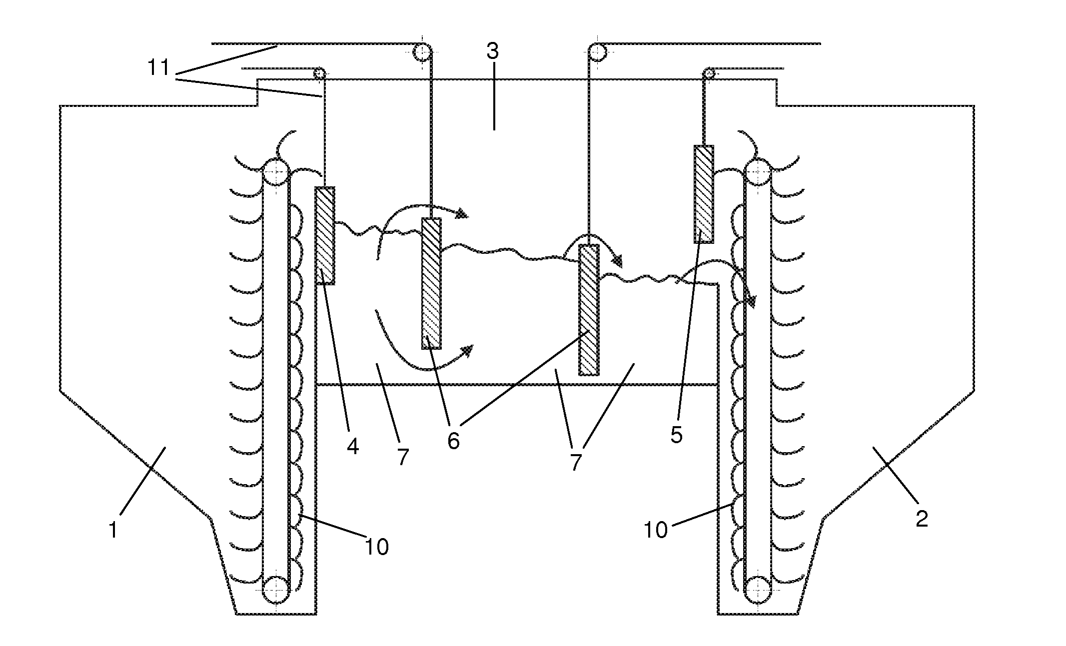
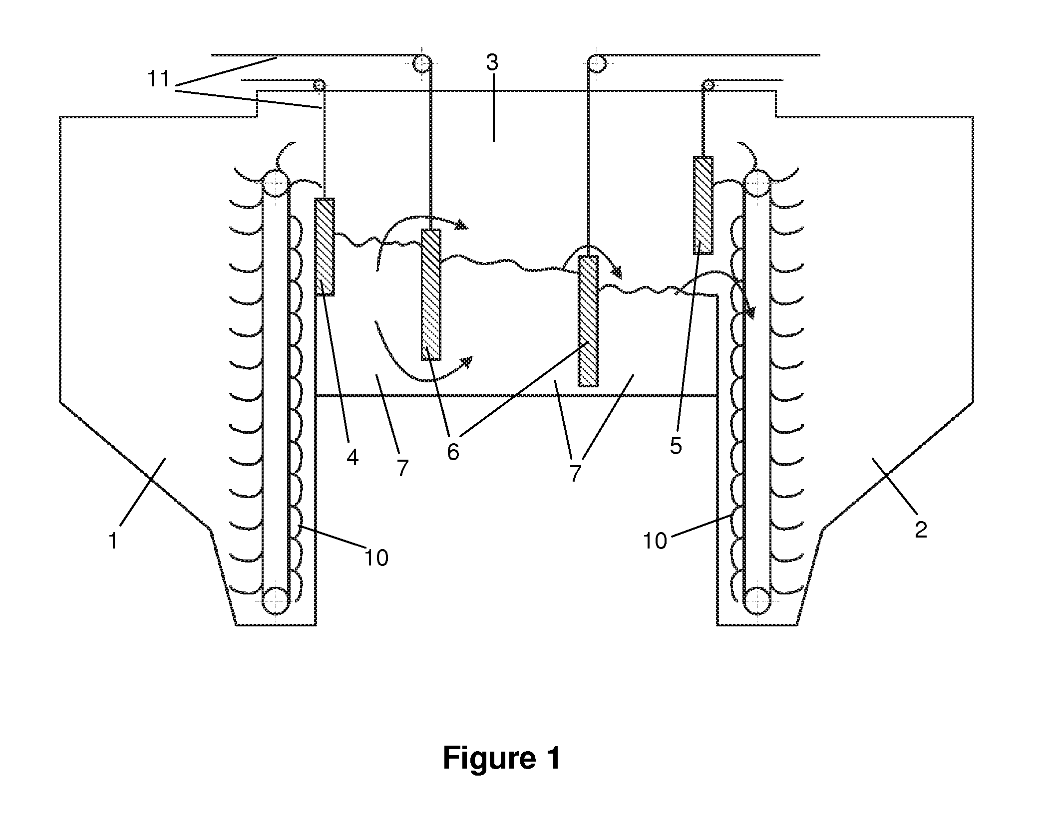
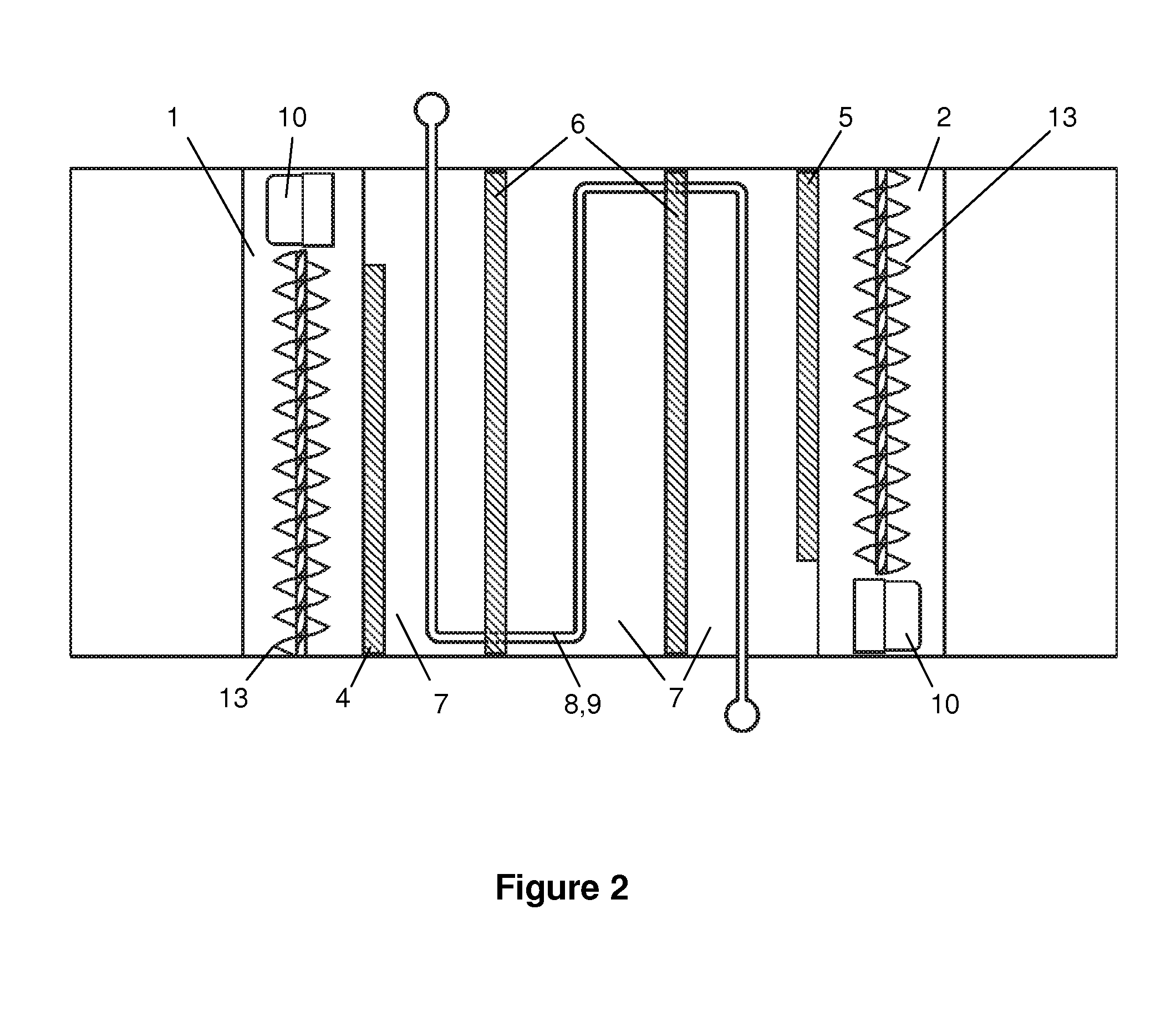
[0040]The figures schematically show preferred embodiments of the heat storage system of the present invention with vertically adjustable weirs. Of course, these embodiments are not intended as limitation but only serve for an illustration of the invention.

[0041]In FIG. 1, reference 1 indicates a storage tank for cold sand, 2 indicates a storage tank for hot sand, 3 indicates the fluidized bed heat exchanger, which is divided into three chambers 7. The division is achieved by means of two weirs 6, and the delimitation towards the storage tanks 1 and 2 is provided by two weirs 4 and 5. All weirs are vertically adjustable by means of chain or rope hoists 11, and each storage tank comprises a bucket or pan hoister 10 for delivering the sand stored therein. The fluidized bed heat exchanger 3 is fluidized by means of a blower (not shown), which blows a fluidizing medium into the heat exchanger 3 from below in order to create fluidized beds in the chambers 7, the average height of which i...


PUM


Abstract

The invention relates to a heat storage system using sand as a solid heat storage medium, characterized in that it comprises the following components: a storage tank (1) for cold sand; a storage tank (2) for hot sand; a fluidized bed heat exchanger (3) arranged therebetween, which is separated from the storage tanks (1, 2) by weirs (4, 5) and divided into a plurality of chambers (7) by weirs (6), wherein the weirs (4, 5, 6) are arranged as a combination of overflow and underflow weirs; wherein means (8) for transferring heat from a heat source to the sand fluidized therein as well as means (9) for transferring heat from the sand fluidized therein to a heat transport medium are provided in the chambers (7) of the heat exchanger (3); and at least one blower (14) positioned underneath the heat exchanger (3) for fluidizing the sand.

Description

STATE OF THE ART[0001]The use of sand as a heat carrier or storage medium is generally known. For example, U.S. Pat. No. 4,338,919 A discloses a solar collector system, wherein a particulate energy collecting medium such as sand flows through a solar collector and thereby absorbs thermal energy. In a fluidized bed heat exchanger, this energy is transferred to a gaseous (e.g. air) or liquid medium (e.g. water), whereafter the solid is again passed through the solar collector.[0002]In contrast to this, DE 101 49 806 C2 formally envisages an additional heat transfer medium between the solar collector and the sand, as well as a sand storage system. Specifically, this document provides a solar power tower in which a mirror heliostat field focusses sunlight to a radiation receiver, thereby heating it. Air flows through the radiation receiver positioned at the spire of the tower, which air absorbs heat and then contacts sand flowing through in counterflow direction within a heat exchanger ...

Claims


Application Information

Patent Timeline
Patent Type & Authority Applications(United States)
IPC IPC(8): F24J2/34F28D19/00F28D17/00
CPCF28C3/16F28D13/00F28D19/02F28D19/00Y02E60/142F24J2/34F28D17/005F28D20/0056Y02P90/50F24S60/00Y02E10/40Y02E60/14
Inventor HAIDER, MARKUSEISL, ROLANDHOLZLEITHNER, FRANZ
Owner VIENNA UNIVERSITY OF TECHNOLOGY
Why Eureka
Try Eureka