Methods and apparatus for aeration of liquid medium and vectoring flow control

Active Publication Date: 2013-08-29
GALLETTA JR ROBERT J
View PDF8 Cites 9 Cited by
  • Summary
  • Abstract
  • Description
  • Claims
  • Application Information

AI Technical Summary

Benefits of technology

[0085]Another feature of the methods and apparatus for aeration of liquid medium and vectoring flow control is its ability to enable inlet water to be acquired at one strata (level) and discharge outlet water to be released or discharged at another strata (level). This is very valuable especia

Problems solved by technology

The wastewater usually includes large amounts of organic and inorganic waste material that, if left untreated, creates severe odors and can generates toxic products.
The Agency developed these criteria because hypoxia (low dissolved oxygen) is a significant problem for lakes, streams, rivers, and coastal waters that receive a lot of runoff that contain nutrients (for example, nitrogen and phosphorous and other oxygen-demanding biological wastes).
Long periods of DO below 5 mg/L can harm larva life stages for many fish, shellfish, and other aquatic life populations.
If the DO conditions at a site are below the juvenile/adult survival criterion (2.3 mg/L), there is not enough DO to protect aquatic life.
If oxygen is the source, then the oxygen that makes it to the surface of the wastewater pond is wasted as it vents to the air above the pond.
In addition, all such devices mix wastewater

Method used


Image

  • Methods and apparatus for aeration of liquid medium and vectoring flow control
  • Methods and apparatus for aeration of liquid medium and vectoring flow control
  • Methods and apparatus for aeration of liquid medium and vectoring flow control

Examples


Embodiment Construction

[0116]In describing embodiments of an apparatus and method for mixing gas and liquid, as illustrated in FIGS. 1-19, specific terminology is employed for the sake of clarity.

[0117]The disclosure, however, is not intended to be limited to the specific terminology so selected, and it is to be understood that each specific element includes all technical equivalents that operate in a similar manner to accomplish similar functions.

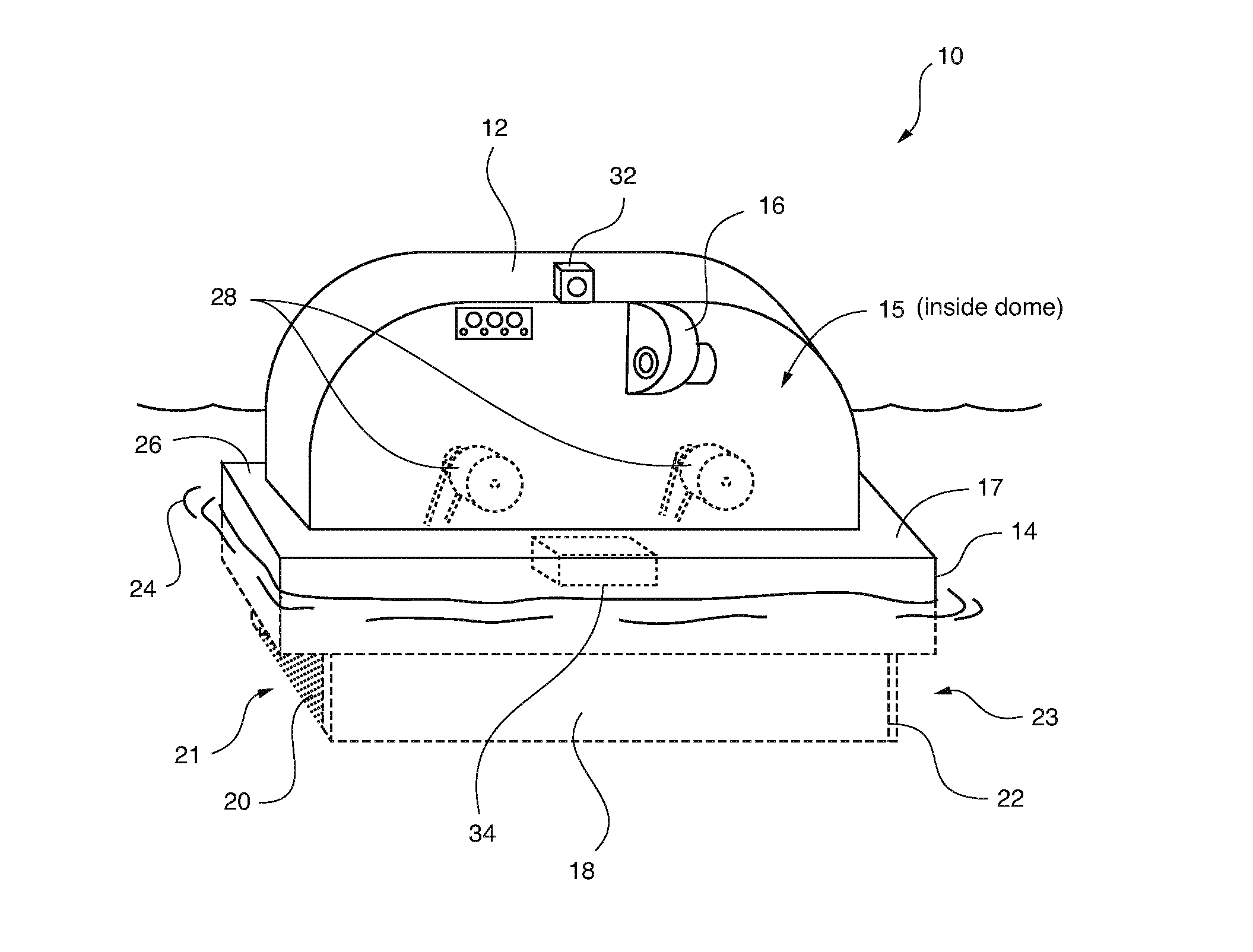
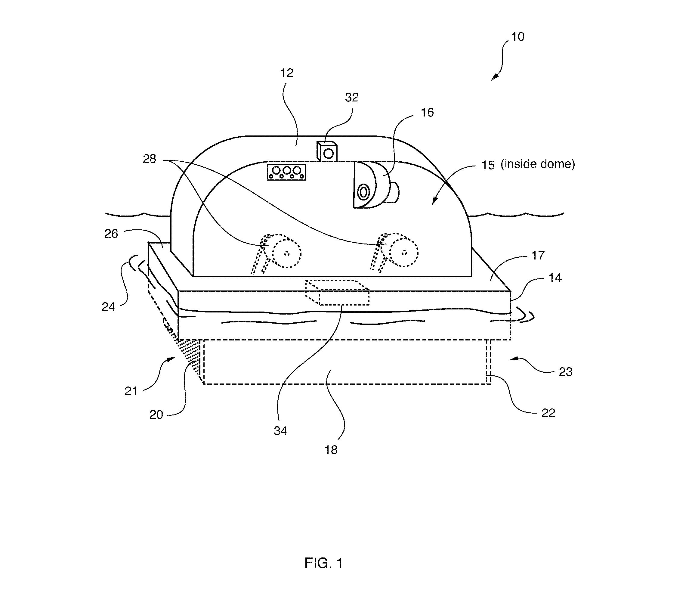
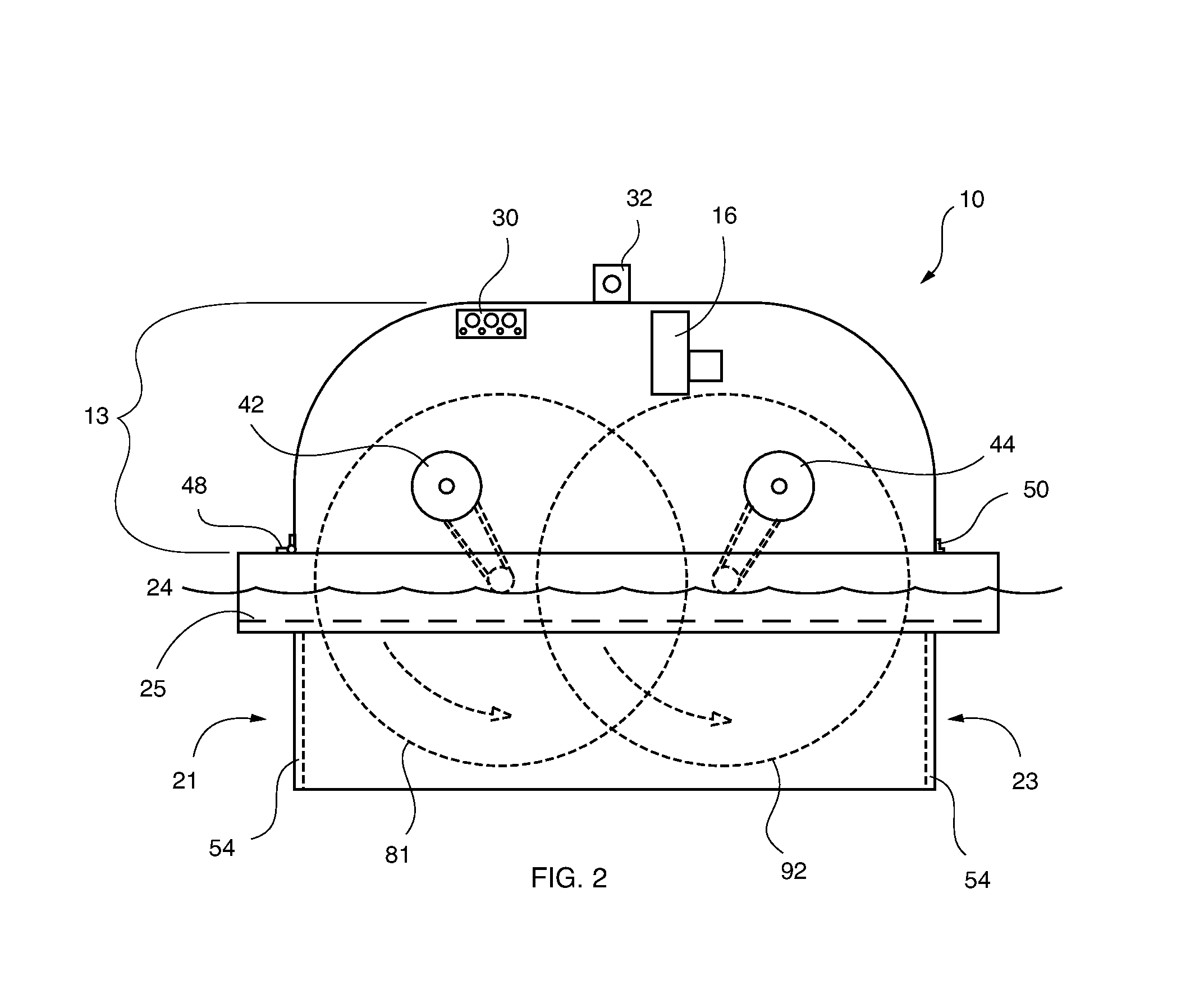
[0118]Referring now to FIGS. 1-19, there is illustrated a floating pressurized dome aerator device and process for adding dissolved gas, such as oxygen, into liquid, such as fresh, salt and brackish water, wastewater, sewage and industrial waste. It is important to understand that the apparatus and method for mixing gas and liquid is suitable for utilization in any liquid environment where an increase in dissolved air or gas into liquid medium is desired or beneficial; therefore, while the apparatus and method for mixing gas and liquid is described conveniently ...


PUM

PropertyMeasurementUnit
Timeaaaaaaaaaa
Flow rateaaaaaaaaaa
Depthaaaaaaaaaa

Abstract

A method and apparatus for vectoring flow control and aeration of a liquid medium, includes a dome supported by a flotation device, a lower housing supported by said flotation device, said lower housing connected to said dome, wherein a space is defined under said dome and above the flotation liquid, an aeration apparatus positioned within said space and partially submerged in the flotation liquid, wherein said aeration apparatus comprises one or more parallel shafts, at least one first disc positioned axially on one of said shafts, at least one second disc positioned axially on another of said shafts, wherein said second disc is interleaved relative to said first disc, and wherein a surface of said first disc rotates in a direction opposite a surface of said second disc relative to each other resulting in a mixing area therebetween, and a discharge chute configured to discharge the liquid medium.

Description

CROSS-REFERENCE AND PRIORITY CLAIM TO RELATED APPLICATIONS[0001]To the fullest extent permitted by law, the present United States Non-Provisional patent application is a continuation-in-part of, and hereby claims priority to and the full benefit of U.S. Non-Provisional patent application entitled, “Controlled Scrubbing and Aeration of Liquid Medium,” filed on Feb. 7, 2013, having assigned Ser. No. 13 / 761,269 (a continuation-in-part of application Ser. No. 12 / 840,017, filed on Jul. 20, 2010), which claims priority to and the full benefit of U.S. Non-Provisional patent application entitled, “Method and Apparatus for Controlled Aeration of Liquid Medium in a Pipe,” filed on Jul. 20, 2010, having assigned Ser. No. 12 / 840,017 (a continuation-in-part of application Ser. No. 12 / 555,786, filed on Sep. 8, 2009), which claims priority to and the full benefit of U.S. Non-Provisional patent application entitled, “Method and Apparatus for Submersible or Self Contained Aeration of Liquid Medium,”...

Claims


Application Information

Patent Timeline
IPC IPC(8): B01F3/04C02F7/00
CPCB01F3/0451C02F7/00B01F13/0049B01F13/065C02F3/14C02F3/1284B01F2003/04872B01F2215/0052B01F3/04765Y02W10/37Y02W10/10B01F23/23231B01F23/2342B01F23/237611B01F33/503B01F33/71B01F2101/305
Inventor GALLETTA, JR., ROBERT J.
Owner GALLETTA JR ROBERT J
Why Eureka
Try Eureka