
Motor drive apparatus equipped with dynamic braking control unit

a technology of dynamic braking and control unit, which is applied in the direction of dynamo-electric converter control, motor/generator/converter stopper, ac motor stopper, etc., can solve the problems of increasing maintenance cost, arc discharge or glow discharge, and significant deformation of contact life, so as to shorten the braking time in dynamic braking and reduce the cost. , the effect of simple construction

Active Publication Date: 2013-08-29
FANUC LTD
View PDF6 Cites 29 Cited by
  • Summary
  • Abstract
  • Description
  • Claims
  • Application Information

AI Technical Summary

Benefits of technology

The present invention aims to provide a motor drive apparatus that is cost-effective and easy to use. It also aims to shorten the braking time in dynamic braking and extend the life of the mechanical contacts used to short-circuit the motor windings of the synchronous motor when applying dynamic braking.

Problems solved by technology

However, if closing the mechanical contacts is attempted while a high voltage is being applied between the contacts, a spark due to an arc discharge or glow discharge occurs between the contacts during the chattering.
Since such a spark may fuse the mechanical contacts to each other or may wear the mechanical contacts, there has been the problem that the contact life significantly degrades, increasing the maintenance cost due to frequent replacement of the contacts, etc.
There has also been the problem that in order to avoid such fusing or wearing of the mechanical contacts, mechanical contact components having a large contact capacity have to be used, which not only increases the cost but also makes it difficult to reduce the size of the apparatus.
However, in this case, in addition to the dynamic braking semiconductor switches, an insulated primary power supply for operating the semiconductor switches and an insulated control circuit for on-off control of the semiconductor switches have to be provided in the short-circuiting unit; there has therefore been the problem that this method not only increases the cost but also makes it difficult to reduce the size of the apparatus, compared with the method that implements the dynamic braking using mechanical contact components such as relays or magnetic contactors.
However, since the rotational energy of the synchronous motor is converted into Joule heat by using only the resistance of the motor windings, there has been the problem that the braking time increases, compared with the case of the dynamic braking based on the mechanical contacts that also uses the dynamic braking resistors.
However, according to the technique disclosed in Japanese Patent No. 3279102, when switching the process from the first half to the second half, if the contacts of the dynamic braking relay are closed while the power transistors are held in the OFF state, which means that the contacts are closed while the induced voltage is being applied, then a spark is generated, causing the contacts to be fused together or the mechanical contacts to wear, and hence the problem that the contact life significantly degrades.
Furthermore, according to the technique disclosed in Japanese Patent No. 3279102, when applying dynamic braking, the power transistors are controlled on and off so as to maintain the armature current constant; this requires the provision of a dynamic braking control circuit including an armature current detector, a rectifier, an adder, a comparator, a delay, etc., and hence the problem that the circuit configuration becomes complex and the cost increases.

Method used


Image

  • Motor drive apparatus equipped with dynamic braking control unit
  • Motor drive apparatus equipped with dynamic braking control unit
  • Motor drive apparatus equipped with dynamic braking control unit

Examples


Embodiment Construction

[0047]A motor drive apparatus equipped with a dynamic braking control unit will be described below with reference to the drawings. It should, however, be understood that the present invention is not limited to the accompanying drawings, nor is it limited to the particular embodiments described herein.

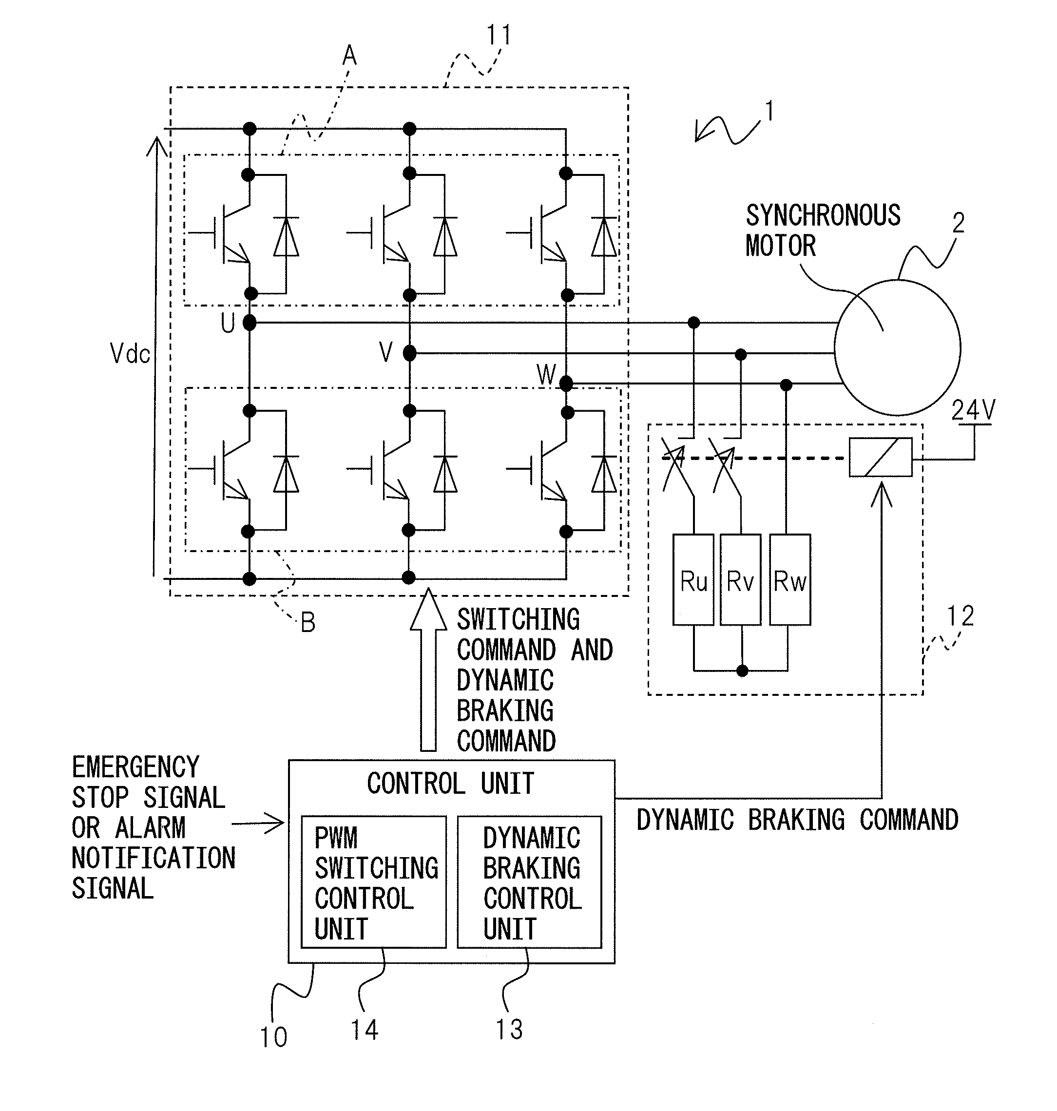
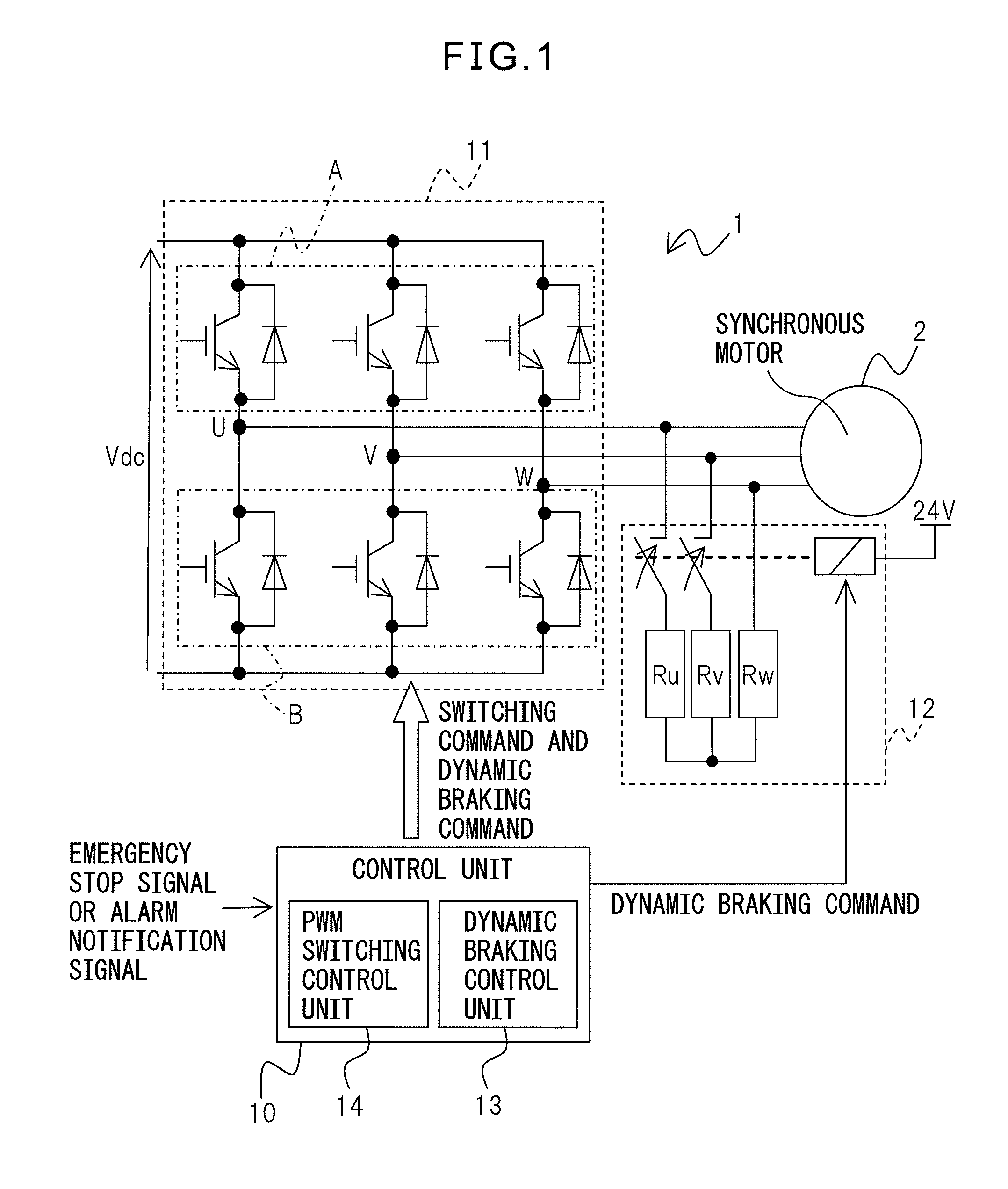
[0048]First, the circuit configuration of the motor drive apparatus will be described. FIG. 1 is a diagram showing the circuit configuration of the motor drive apparatus. The motor drive apparatus 1 which converts DC to AC to provide drive power for driving a synchronous motor 2 includes a full-bridge inverter 11 which has an upper arm A and a lower arm B each provided with semiconductor switching devices (power transistors) and free-wheeling diodes connected in reverse parallel with the respective semiconductor switching devices, wherein the semiconductor switching devices are controlled on and off to convert DC to AC, a short-circuiting unit 12 which includes a selector switch between...


PUM


Abstract

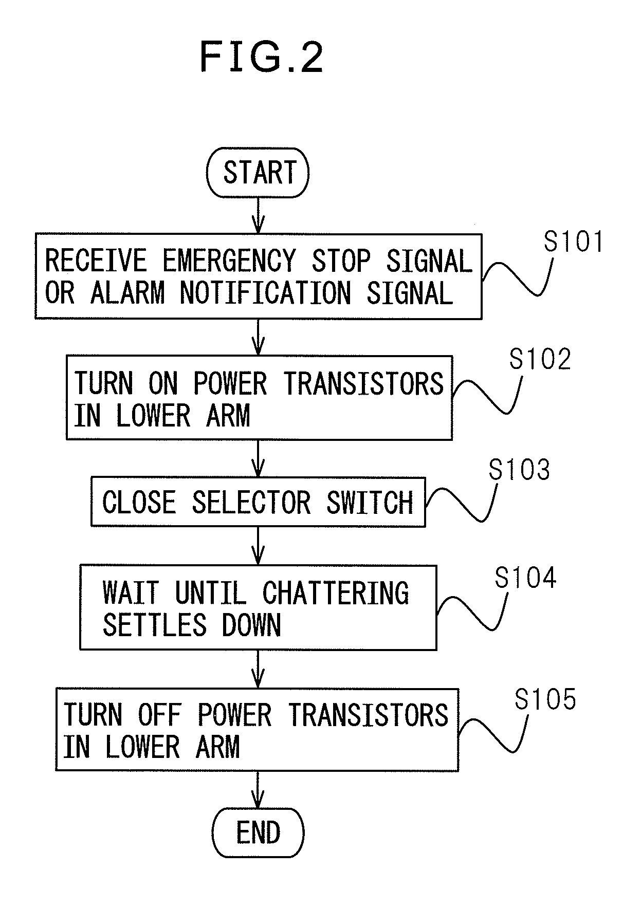
A motor drive apparatus includes an inverter which has an upper and lower arms each provided with a plurality of semiconductor switching devices and free-wheeling diodes connected in reverse parallel with respective ones of the plurality of semiconductor switching devices, wherein the semiconductor switching devices are controlled on and off to convert DC to AC, a short-circuiting unit which includes a selector switch between motor phase windings of a synchronous motor, the selector switch being opened and closed under the control of a command, and a dynamic braking control unit which, upon reception of a dynamic braking start command, performs control so as to turn on all of the semiconductor switching devices provided in either one of the upper and lower arms and to turn off all of the semiconductor switching devices provided in the other arm, and thereafter controls the short-circuiting unit so that the selector switch is closed.

Description

BACKGROUND OF THE INVENTION[0001]1. Field of the Invention[0002]The present invention relates to a motor drive apparatus equipped with a dynamic braking control unit.[0003]2. Description of the Related Art[0004]In a motor drive apparatus for driving a synchronous motor used to drive a feed shaft of a machine tool or industrial machine or an industrial robot or the like, dynamic braking that produces a dynamic braking force by short-circuiting the motor windings of the synchronous motor is widely used in the case of an emergency stop or in an emergency such as occurrence of an alarm (warning). If electrically disconnected from the power supply, the synchronous motor which uses a permanent magnet retains a magnetic field flux, and the rotating motor acts as a generator; therefore, dynamic braking can be applied by short-circuiting the windings of the rotating motor.[0005]In dynamic braking, from the standpoint of reducing the braking distance and braking time by generating as large a ...

Claims


Application Information

Patent Timeline
Patent Type & Authority Applications(United States)
IPC IPC(8): H02P27/06H02P3/18H02P3/22
CPCH02P3/22H02P27/06
Inventor HORIKOSHI, SHINICHISATO, HIROYASUKOBAYASHI, MINORU
Owner FANUC LTD
Learn More