Virtual image display apparatus

a virtual image and display device technology, applied in the field of virtual image display devices, can solve the problems of insufficient external light, observer's uneasy feeling, and observer's inability to judge the status of the external world, and achieve the effect of wide angle of view and high performan

Active Publication Date: 2013-08-29
SEIKO EPSON CORP
View PDF4 Cites 171 Cited by
  • Summary
  • Abstract
  • Description
  • Claims
  • Application Information

AI Technical Summary

Benefits of technology

[0012]An advantage of some aspects of the invention is to provide a compact and light-weight virtual image display apparatus which has a wide angle of view and high performance, and a see-through function that superimposes and displays an external light and an image light.

Problems solved by technology

In addition, in a state in which the observer's view is totally covered and only the image light is viewed, the observer cannot judge the status of the external world, therefore the observer feels uneasy.
However, this type of optical system in the related art is not designed such that the external light is intended to be viewed by the observers, and thus the prism in front of eyes is small, so a sufficient external light is not received.
Further, since the shape of the curved surface which transmits the external light is not suitable, the diopter scale with respect to the external world does not become zero and thus blurring and distortion occur.
However, the optical system in JP-A-2008-158203 uses a hologram in a half mirror surface, so that an aberration or wavelength selectivity due to this gives an effect to an image light, and thereby lowering the image quality.
If the value exceeds the upper limit of the condition (1), the shape is approximate to the flat surface, so that the aberration correction of the image light may not be efficiently performed even in the case where there is no problem in observing the external light.
If the value exceeds the lower limit of the condition (1), the curvature is strong, so that it is difficult to perform the aberration correction, and the position of the prism of the relay optical system is close to the face, so a sense of wearing becomes bad.
If the difference exceeds the upper limit of the condition (2), the astigmatism which is generated in the third surface becomes too large, so that the aberration correction becomes difficult.

Method used


Image

  • Virtual image display apparatus
  • Virtual image display apparatus
  • Virtual image display apparatus

Examples


first embodiment

[0075]Hereinafter, referring to drawings, a first virtual image display apparatus of a first embodiment related to the invention will be described in detail.

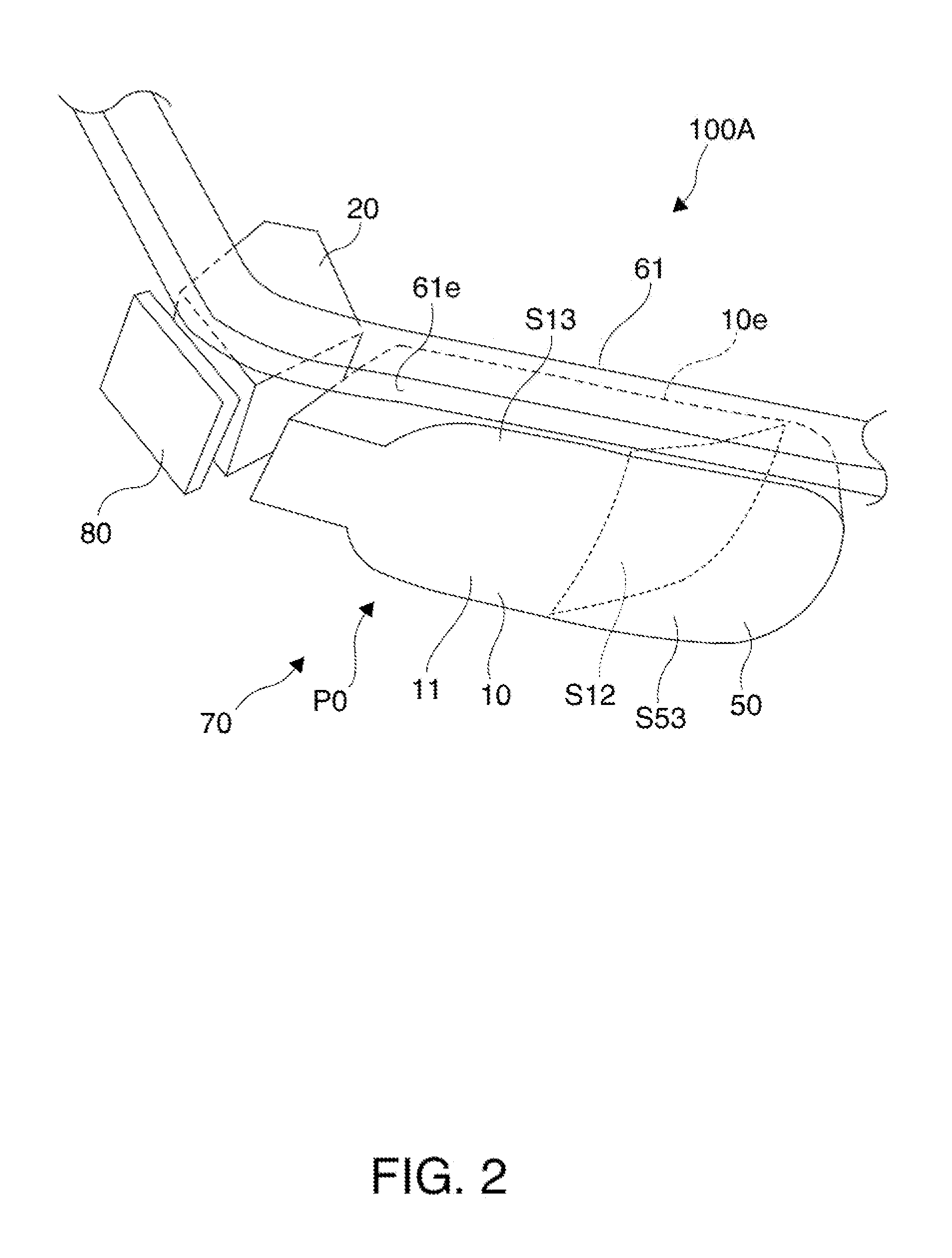
A. Appearance of First Virtual Image Display Apparatus

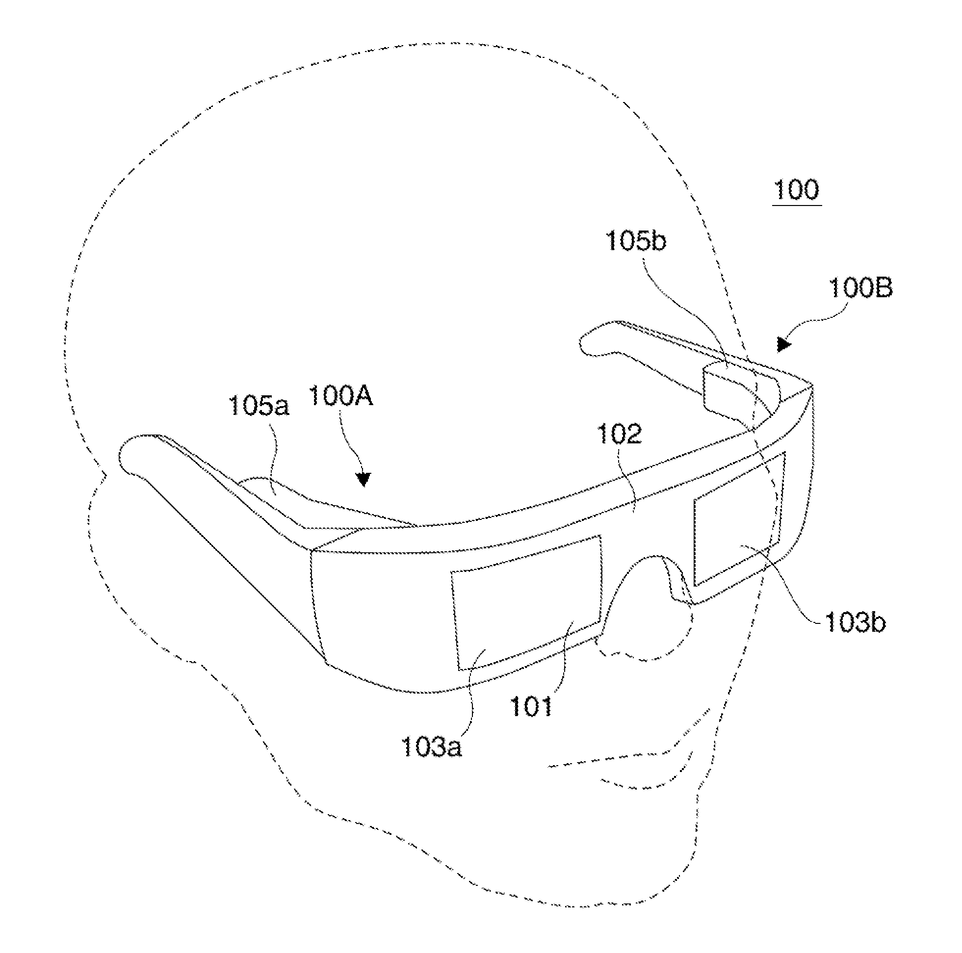
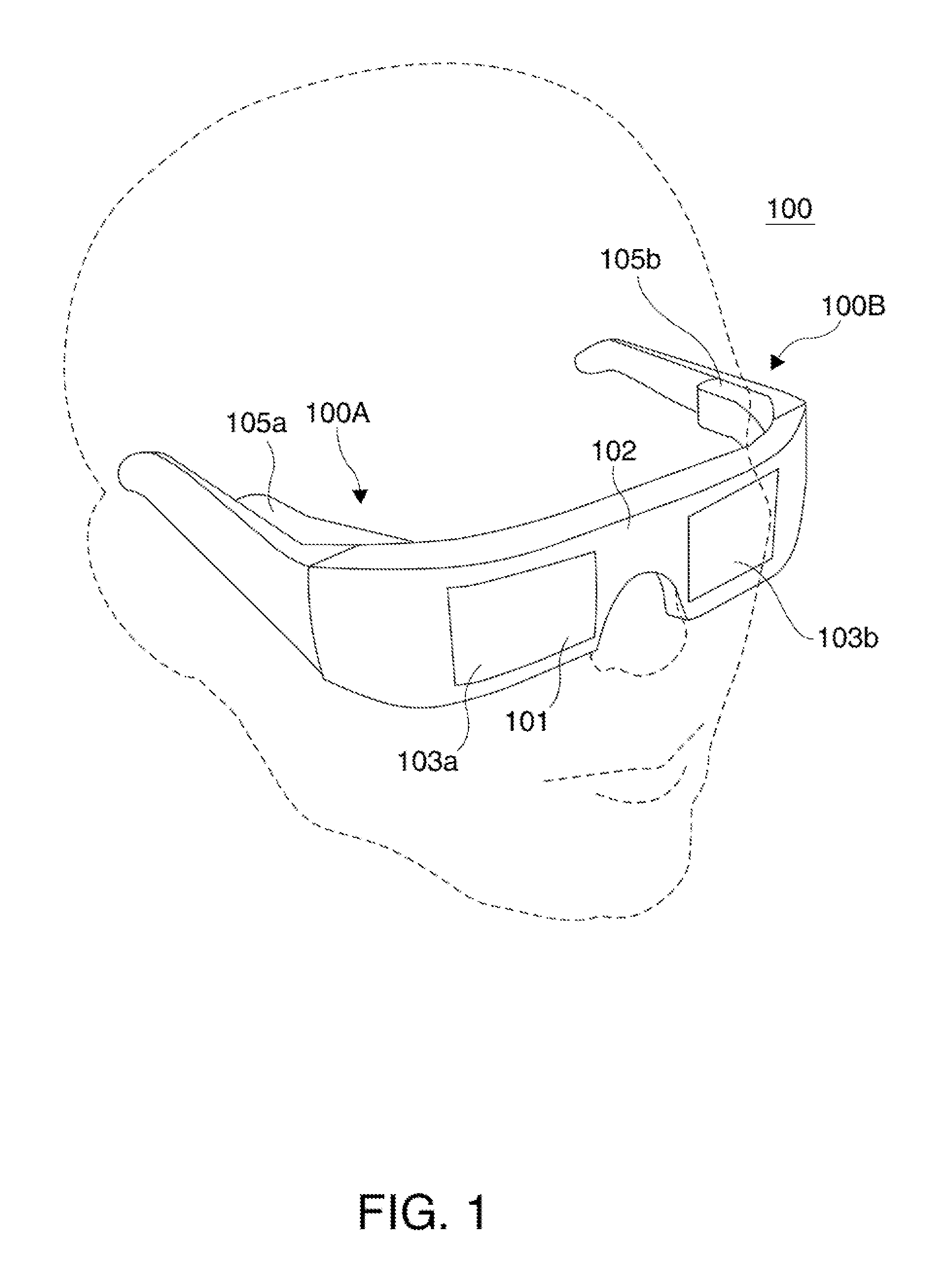
[0076]The first virtual image display apparatus 100 shown in FIG. 1 is a head mount display having an appearance of the glasses, and enables an observer who wears the virtual image display apparatus 100 to visually recognize an image light corresponding to a virtual image and the observer to see or observe an external image in a see-through manner. The virtual image display apparatus 100 includes a see-through member 101 which covers the eye in front of the observer, a frame 102 for supporting the see-through member 101, and first and second built-in apparatus portions 105a and 105b added to a portion from a cover portion in both of a left and a right edge of the frame 102 to rear bow portion (temple). Here, the see-through member 101 is an optical member (a transmitting eye ...

examples of first embodiment

[0120]Hereinafter, Examples of the perspective projection device which is incorporated in a first virtual image display apparatus according to the invention will be described. The symbols used in each Example are arranged below.

[0121]SPH: a pupil

[0122]FFSk: a free curved surface (k in the prism=the number of the surface)

[0123]SPH: a sphere shape or a flat surface (the surface of a protective glasses)

[0124]R: a radius of curvature

[0125]T: a distance between surfaces on the axis

[0126]Nd: a refractive index with respect to d line of an optical material

[0127]Vd: Abbe number with respect to d line of an optical material

[0128]TLY: an inclination angle (°) of an optical axis in a lateral cross section (XZ cross section) of a certain surface (TLY may change before and after the certain surface)

[0129]DCX: a deviation amount of an optical axis of X axis direction in a lateral cross section (XZ cross section) of a certain surface

example 1

[0130]Data of optical surfaces constituting the first and second prisms in a perspective projection device of Example 1 is shown in Table 1. Further, for example, FFS1 means the first surface S11, FFS2 means the second surface S12, and FFS3 means the third surface S13.

TABLE 1NoTypeRTNdVd1SPH∞20.002FFS1−93.5395.501.52555.953FFS2−52.343−5.501.52555.954FFS1−93.5399.001.52555.955FFS3−93.539−12.001.52555.956FFS4−7.126−2.007FFS5−25.191−12.001.52555.958FFS648.79310.001.52555.959FFS7−19.626−11.001.52555.9510FFS8955.532−3.0011SPH∞−1.601.45867.8212ImageSurface

[0131]With respect to optical surfaces in a prism constituting Example 1, an optical axis inclination angle (tilt) TLY and an optical axis deviation amount (decenter) DCX in the lateral cross section are shown in Table 2 below.

TABLE 2TLY(BeforeDCX(AfterTLY(AfterNoTypeSurface)Surface)Surface)2FFS10003FFS2−280284FFS10005FFS3020.367−42.196FFS40007FFS50008FFS6−210−219FFS7−220−2210FFS8000

[0132]With regard to each of optical surfaces in the pr...


PUM


Abstract

An intermediate image is formed inside a first prism, and an image light, which is reflected on the order of a third surface, a first surface and a second surface, is transmitted through the first surface and reaches the eyes of the observer, therefore it is possible to make the entire optical system small and light in weight by making the first prism thin, and realize a high performance display device with a wide angle of view. Further, when an external light is passed through, for example, the first surface and the third surface and observed, a diopter scale is set to approximately zero, and thereby reducing the defocus or distortion of the external light when observed in a see-through manner. And, it is possible such that the shape of the first prism conforms to the face of the observer, the center is also close to the face.

Description

BACKGROUND[0001]1. Technical Field[0002]The present invention relates to a virtual image display apparatus which presents an image formed by an image display element and the like to an observer, and in particular to a virtual image display apparatus suitable for a head mount display to be mounted on the head of the observer.[0003]2. Related Art[0004]As an optical system which is incorporated in a virtual image display apparatus such as a head mount display (hereinafter, referred to as an HMD) to be mounted in the head of an observer, various optical systems have been proposed (refer to JP-A-2000-66106, JP-A-2000-131614, JP-A-2000-299853 and JP-A-2004-341411).[0005]With regard to the virtual image display apparatus such as the HMD, it is desirable to have a wide angle of view of an image light and to reduce the weight of the apparatus. In particular, thinning the thickness in a visual axis direction of the observer and making a central point close to the observer are very important i...

Claims


Application Information

Patent Timeline
Patent Type & Authority Applications(United States)
IPC IPC(8): G02B27/01
CPCG02B27/01G02B27/0172G02B2027/011G02B2027/0178
Inventor KOMATSU, AKIRATOTANI, TAKAHIROTAKEDA, TAKASHIMIYAO, TOSHIAKITAKAGI, MASAYUKI
Owner SEIKO EPSON CORP
Why Eureka
Try Eureka