High frequency piezoelectric crystal composites, devices, and methods for manufacturing the same

a piezoelectric crystal and composite technology, applied in the direction of niobium compounds, device material selection, crystal growth process, etc., can solve the problems of failure to adjust, decrease of piezoelectric materials, operative and electromechanical difficulties, etc., and achieve the effect of improving performan

Active Publication Date: 2013-08-29
CTS CORP ELKHART
View PDF0 Cites 2 Cited by
  • Summary
  • Abstract
  • Description
  • Claims
  • Application Information

AI Technical Summary

Benefits of technology

[0018]The present invention generally relates to high frequency piezoelectric crystal composites, devices, and method for manufacturing the same. In adaptive embodiments an improved imaging device, particularly a medical imaging device or a distance imaging device, for high frequency (>20 MHz) applications involving an imaging transducer assembly is coupled to a signal imagery processor. Additionally, the proposed invention presents a system for photolithography based micro-machined piezoelectric crystal composites and their uses resulting in improved performance parameters.
[0020]It is a further aspect of the present invention that the innovative fabrication approaches make the commercial production of crystal composite feasible and practical. The high frequency crystal composite (20 MHz to >100 MHz, and a thickness electro-mechanical coupling factor kt 0.65-0.90 can be used for medical ultrasound imaging and diagnosis with significantly improved performances. The high frequency crystal composite is especially applicable to use with skin, eye, intravascular, intracardiac, intracranial, intra-cavity or intra-luminal medical diagnosis devices. Such devices may be used in applications involving dermatology, ophthalmology, laparoscopy, intracardiac and intravascular ultrasound.

Problems solved by technology
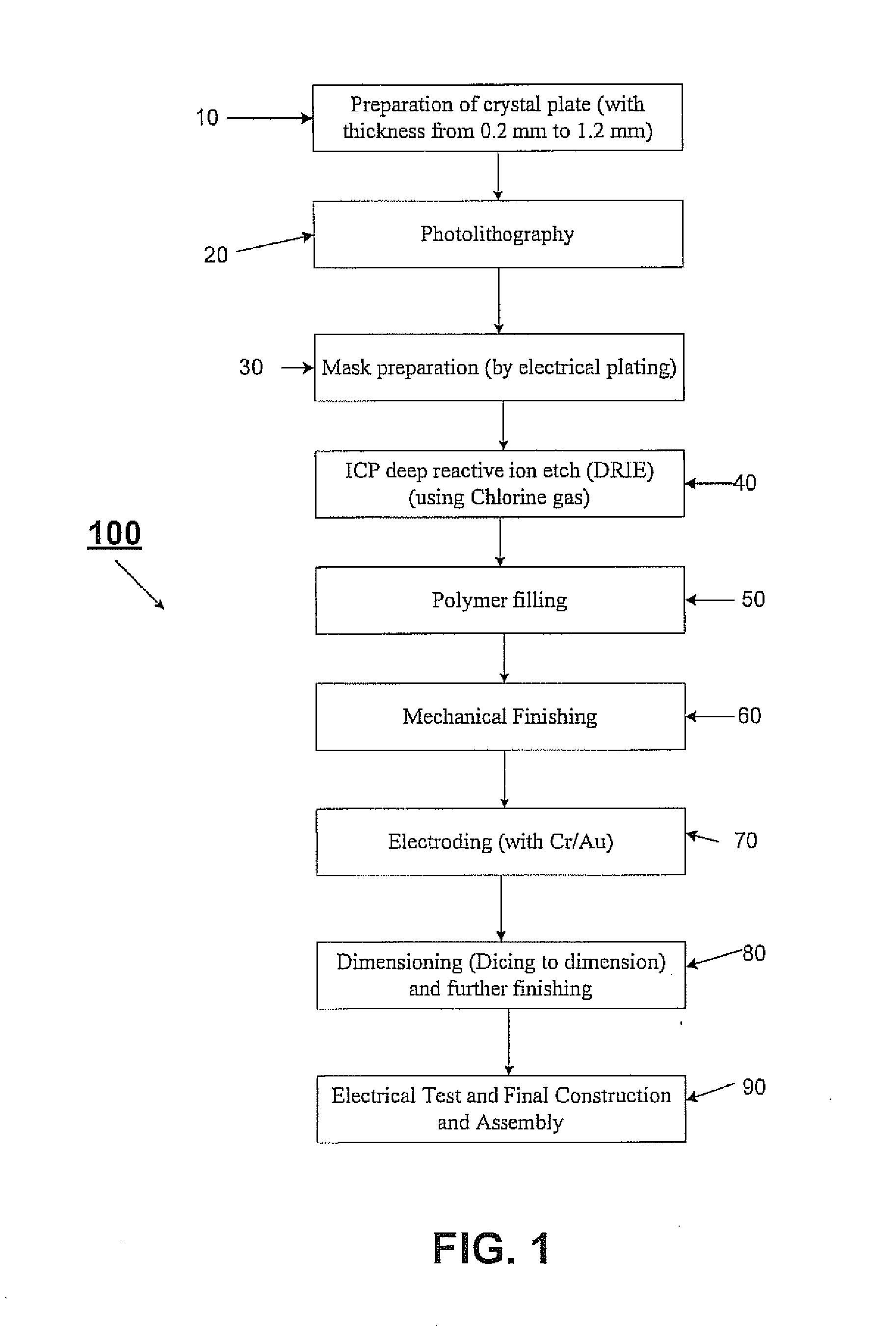
Thus, as the targeted operating frequency increases, the thickness of piezoelectric material decreases accordingly this induces operative and electro mechanical difficulties.
The '853 patent additionally notes the conventional challenges of micromachining poled PZT ceramics, but fails to adjust to the now appreciated challenges noted below and additionally includes the detrimental impacts of electric field and clamping effect on strain.

Method used


Image

  • High frequency piezoelectric crystal composites, devices, and methods for manufacturing the same
  • High frequency piezoelectric crystal composites, devices, and methods for manufacturing the same
  • High frequency piezoelectric crystal composites, devices, and methods for manufacturing the same

Examples


Embodiment Construction

[0044]Reference will now be made in detail to embodiments of the invention. Wherever possible, same or similar reference numerals are used in the drawings and the description to refer to the same or like parts or steps. The drawings are in simplified form and are not to precise scale. For purposes of convenience and clarity only, directional (up / down, etc.) or motional (forward / back, etc.) terms may be used with respect to the drawings. These and similar directional terms should not be construed to limit the scope of the invention in any manner.

[0045]As will be used herein the Miller Indices identifiers serve as vector representations for orientation of an atomic plane in a crystal lattice having three axes represented by a set of 3 integer numbers, for example such conventional identifiers as, for example or , are used.

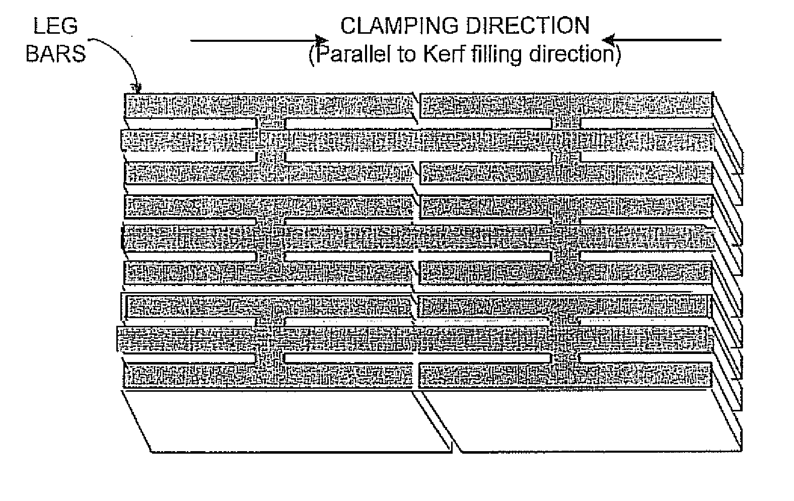
[0046]As will be further used herein, for example regarding the images of the present invention wherein polymeric (epoxy) regions are filled with a piezoelectricall...


PUM

PropertyMeasurementUnit
frequencyaaaaaaaaaa
frequencyaaaaaaaaaa
widthaaaaaaaaaa

Abstract

The present invention generally relates to high frequency piezoelectric crystal composites, devices, and method for manufacturing the same. In adaptive embodiments an improved imaging device, particularly a medical imaging device or a distance imaging device, for high frequency (>20 MHz) applications involving an imaging transducer assembly is coupled to a signal imagery processor. Additionally, the proposed invention presents a system for photolithography based micro-machined piezoelectric crystal composites and their uses resulting in improved performance parameters.

Description

CROSS-REFERENCE TO RELATED APPLICATIONS[0001]This application claims priority from U.S. Prov. Ser. No. 61 / 344,801 filed Oct. 13, 2010, the entire contents of which are incorporated herein by reference.FIGURE SELECTED FOR PUBLICATION[0002]FIG. 3BACKGROUND OF THE INVENTION[0003]1. Field of the Invention[0004]The present invention relates to the field of piezoelectric crystals and piezoelectric crystal composites operating for high frequency (>20 MHz). More particularly, the present invention provides high frequency piezoelectric crystal composites for high resolution imagery for preferred use in industrial and medical ultrasound applications, and even more particularly to the methods of manufacturing the same.[0005]2. Description of the Related Art[0006]Conventionally, PMN-PT based piezoelectric single crystals have superior dielectric and piezoelectric properties compared to the traditional PZT ceramics. To more fully exploit the excellent properties of single crystals, crystal co...

Claims


Application Information

Patent Timeline
Patent Type & Authority Applications(United States)
IPC IPC(8): G03H3/00
CPCA61B8/00C01G33/006C01P2002/50C01P2004/03H01L41/18H01L41/183H01L41/338C30B29/30C30B29/32G03H3/00H01L41/332C04B35/495C04B2235/3236C04B2235/3249C04B2235/768Y10T29/42C04B35/499C04B2235/3286C04B2235/3296C04B2235/3298H10N30/85H10N30/8548H10N30/852H10N30/082H10N30/088C01G23/00C04B35/491H10N30/853H10N30/8554A61B8/4483C04B2235/3206C04B2235/3215C04B2235/3224C04B2235/3234C04B2235/3255C04B2235/76C04B2235/96H03H9/02015
Inventor HAN, PENGDITIAN, JIANMENEOU, KEVINSTONE, BRANDON
Owner CTS CORP ELKHART
Why Eureka
Try Eureka