Electric wire connection structure of connector terminal

a technology of connector terminals and electrical wires, which is applied in the direction of permanent deformation connections, line/current collector details, and connection between dissimilar metals, which might undergo electric corrosion of the junction between dissimilar metals, and poses difficulty or impedes the insertion of the terminal, etc., to achieve the effect of reducing the corners of the crimping pieces that bite into the electric wire, preventing corrosion, and enhancing the adhesion between the interior surface of the electric wire connection section

Active Publication Date: 2013-08-29
YAZAKI CORP
View PDF8 Cites 14 Cited by
  • Summary
  • Abstract
  • Description
  • Claims
  • Application Information

AI Technical Summary

Benefits of technology

[0030]In the electric wire connection structure of the connector terminal having the configuration described in connection with (3), the portion of the end of the electric wire covered with the insulated sheath is crimped along with the exposed conductor by means of the electric wire connection section such that a cross section of the crimped portion covered with the insulated sheath becomes smaller than a cross section of the electric wire that extends backwards from the electric wire connection section. Therefore, even when the electric wire connection section is coated with a resin, the cross section of the electric wire including the resin can be kept small, so that insertion of the connector terminal into the terminal accommodating chamber of the connector housing can be easily, smoothly performed. Further, since the portion of the conductor covered with the insulated sheath is also crimped by the electric wire connection section along with the conductor, the exposed portion of the conductor can be minimized, so that the connection section can be protected against corrosion. Therefore, even when the conductor is covered with a resin, operation for molding and coating the resin can be readily performed.
[0031]In the electric wire connection structure of the connector terminal having the configuration defined in (4), an extent from the extremity of the conductor to the position including the rear end of the electric wire connection section is covered with the resin, and hence the connection section between the conductor and the connector terminal can be protected against electrical corrosion.
[0032]In the electric wire connection structure of the connector terminal having the configuration defined in (5), the chamfered portion is provided in each of the corners where upper edges and rear edges of the pair of crimping pieces cross each other. Therefore, an extent to which the corners of the crimping pieces bite into the electric wire is diminished, thereby inhibiting the insulated sheath of the electric wire from subjecting to flaws.
[0033]In the electric wire connection structure of the connector terminal having the configuration defined in (6), the raised or indented strips on the interior surface of the electric wire connection section bite into the insulated sheath of the electric wire. Hence, adhesion between the interior surface of the electric wire connection section and the insulated sheath can be enhanced. Furthermore, the raised or indented strips extend in a direction crossing a longitudinal direction of the electric wire. Even when water is about to enter deep into the conductor from the rear end of the electric wire connection section, a channel of intrusion of water can be shut off by means of a complicate contact structure formed as a result of the raised or indented strips biting into the insulated sheath, so that intrusion of water can be blocked, and corrosion of the conductor can be inhibited.
[0034]In the electric wire connection structure of the connector terminal having the configuration described in connection with (7), a cross section of the electric wire connection section to which the end of the electric wire is crimped and connected is substantially equal to or smaller than a cross section of the electric connection section. Therefore, the electric wire connection section and its neighborhood would not interfere with the connector housing when the terminal is inserted into the terminal accommodating chamber of the connector housing, and easy insertion of the connector terminal can be effected.
[0035]According to the present invention, even when the electric-wire-connected portion is covered with a resin, a connector terminal can be readily inserted into a terminal accommodating chamber of the connector housing. In a state where the connector terminal remains accommodated in the connector housing, there can be eliminated the possibility of corrosion of a conductor of an electric wire or electrical corrosion of a junction, which would otherwise occur when the terminal and the conductor of the electric wire are formed from dissimilar metals, and waterproofness of the conductor can also be enhanced.

Problems solved by technology

For instance, when the connector terminal is formed from copper or a copper alloy, a junction between dissimilar metals might undergo electric corrosion when moisture attaches to the junction.
Accordingly, when the terminal is about to be inserted into the terminal accommodating chamber of the connector housing, the portion covered with the resin interferes with the connector housing, which often poses difficulty on or impedes insertion of the terminal.
When this portion becomes too large, ease of insertion of the terminal into the terminal accommodating chamber becomes often deteriorated.

Method used


Image

  • Electric wire connection structure of connector terminal
  • Electric wire connection structure of connector terminal
  • Electric wire connection structure of connector terminal

Examples


first embodiment

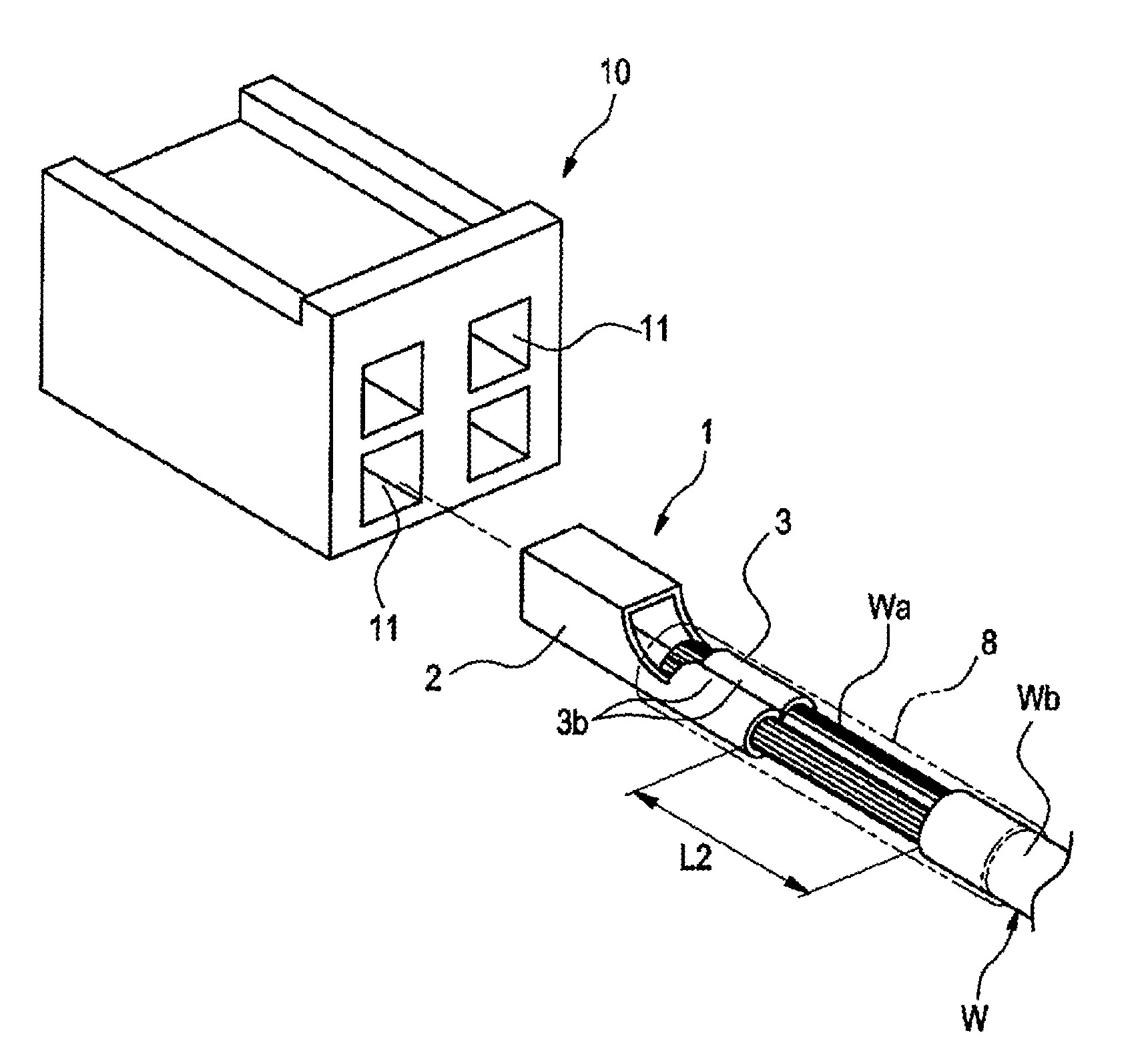
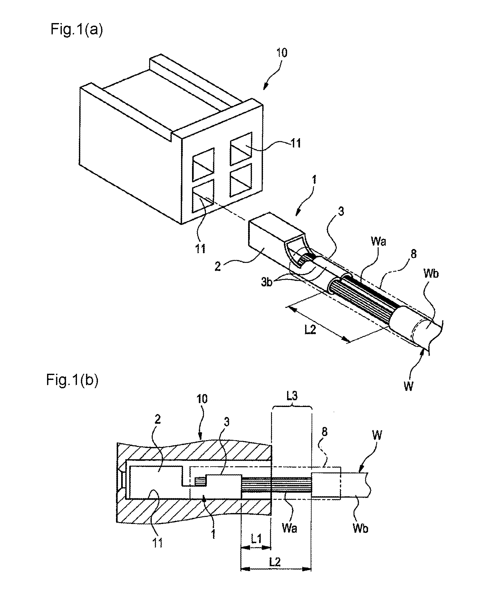
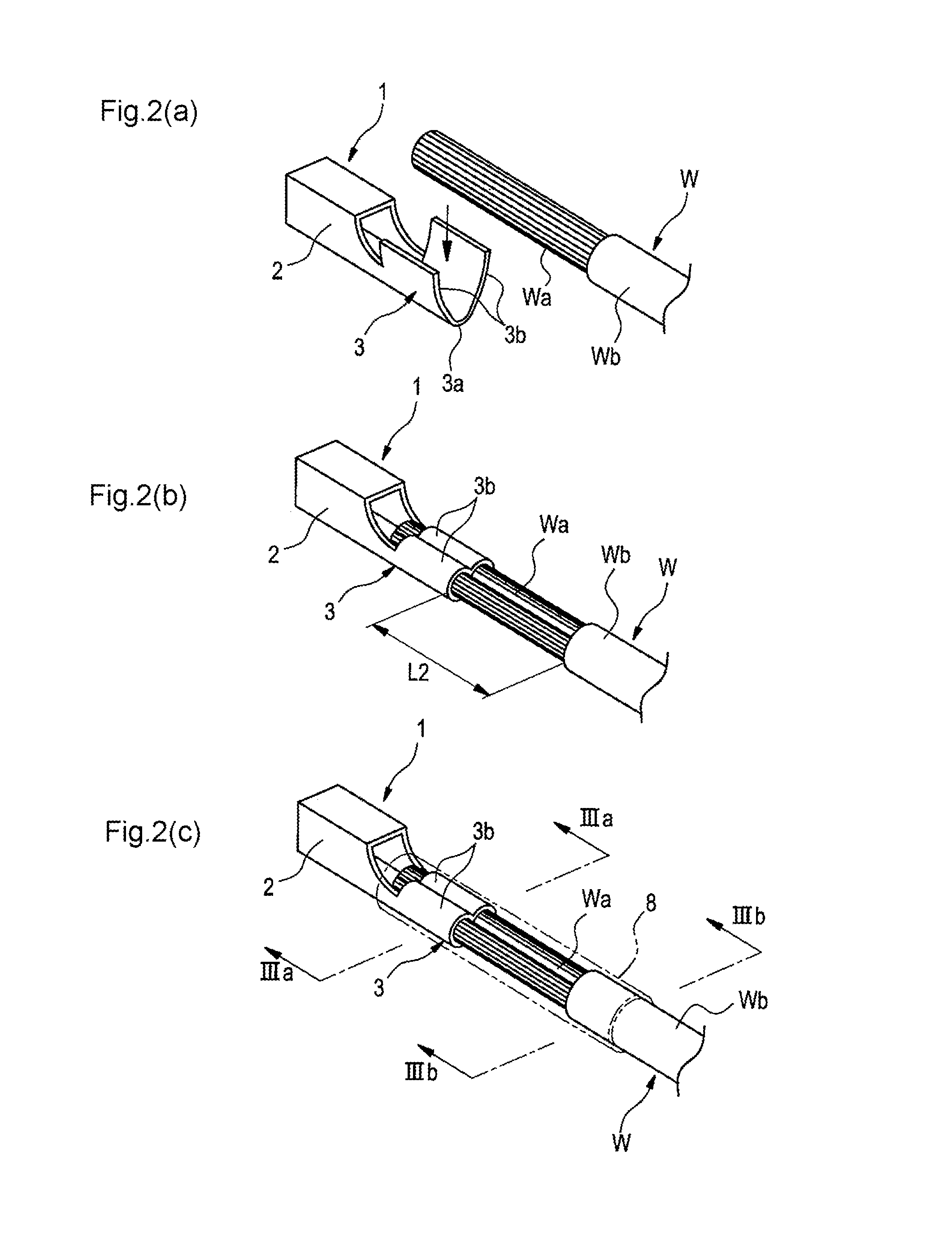
[0053]FIG. 1(a) and FIG. 1(b) show an electric wire connection structure of a connector terminal of a first embodiment, wherein FIG. 1(a) is a perspective view showing that a connector terminal with an end of an electric wire is about to be inserted into a terminal accommodating chamber of a connector housing, and FIG. 1(b) is a side cross sectional view of the terminal accommodating chamber into which the connector terminal is inserted. FIG. 2(a) to FIG. 2(c) are explanatory flow diagrams through which the electric wire connection structure of the embodiment is produced, wherein FIG. 2(a) is a perspective view showing that a conductor of an electric wire from which an insulated sheath is cut off is about to be placed on an electric wire connection section of the connector terminal, FIG. 2(b) is a perspective view showing that the electric wire is crimped and connected with crimping pieces of the electric wire connection section after the conductor is placed on the electric wire con...

second embodiment

[0062]FIG. 6(a) to FIG. 6(d) are explanatory views of a second embodiment in which the present invention is applied to a connector terminal, like a common terminal, having a conductor crimping section and a cladding crimping section, wherein FIG. 6(a) is a perspective view showing that a conductor is crimped with the conductor crimping section and the cladding crimping section, FIG. 6(b) is a cross section acquired when viewed along a direction of arrows Vib-Vib shown in FIG. 6(a), FIG. 6(c) is a cross section acquired when viewed along a direction of arrows VIc-VIc shown in FIG. 6(a), and FIG. 6(d) is a perspective view showing that the portion of the connector terminal to which the electric wire is connected is further covered with a resin (designated by chain double-dashed lines).

[0063]The connector terminal 1 used in the first embodiment has only one conductor crimping section as an electric wire connection section. In contrast, an electric wire connection section 3B of a connec...

third embodiment

[0068]FIGS. 7(a) and 7(b) show an electric wire connection structure of a connector terminal of a third embodiment, wherein FIG. 7(a) is a perspective view showing that a connector terminal with an end of an electric wire is about to be inserted into the terminal accommodating chamber of the connector housing, and FIG. 7(b) is a side cross section of the terminal accommodating chamber into which the connector terminal is inserted. FIGS. 8(a) to 8(c) are explanatory flow diagrams through which the electric wire connection structure of the third embodiment is produced, wherein FIG. 8(a) is a perspective view showing that a conductor of an electric wire from which an insulated sheath is cut off is about to be placed on an electric wire connection section of the connector terminal, FIG. 8(b) is a perspective view showing that the electric wire is crimped and connected with crimping pieces of the electric wire connection section after the conductor is placed on the electric wire connecti...


PUM


Abstract

A conductor (Wa) of the electric wire (W) whose insulated sheath (Wb) is removed from an extremity of the conductor to a location where the conductor projects backwards from a rear end of the terminal accommodating chamber (11) of the connector housing 10 is crimped and connected by means of a pair of crimping pieces (3b), and an area that ranges from the extremity of the conductor (Wa) to the location that includes an end of the insulated sheath (Wb) is covered with a resin (8).

Description

CROSS REFERENCE TO RELATED APPLICATION[0001]This application is a continuation of PCT application No. PCT / JP2011 / 071270, which was filed on Sep. 16, 2011 based on Japanese Patent Application No. 2010-229959 filed on Oct. 12, 2010, the contents of which are incorporated herein by reference. Also, all the references cited herein are incorporated as a whole.BACKGROUND OF THE INVENTION[0002]1. Field of the Invention[0003]The present invention relates to an electric wire connection structure of a connector terminal to be inserted into a terminal accommodating chamber of a connector housing from behind.[0004]2. Description of the Related Art[0005]Like an example shown in FIG. 14, a common connector terminal 201 has on its front side an electric connection section 202 to be connected to an un-illustrated counterpart terminal, and the like. Further, the common connector terminal 201 has on its rear side a front-side conductor crimping section 203 and a rear-side cladding crimping section 20...

Claims


Application Information

Patent Timeline
Patent Type & Authority Applications(United States)
IPC IPC(8): H01R4/70H01R4/18
CPCH01R4/70H01R4/185H01R4/18H01R43/048
Inventor SATO, KEIKODAMA, SHINJI
Owner YAZAKI CORP
Why Eureka
Try Eureka