Image processing device, image processing method, and program

a microlens array and image processing technology, applied in the field of microlens array calibration, can solve the problems of inability to obtain deviations in the mounting position of the microlens array from the design value, inability to provide an image refocused accurately at the desired subject distance, and loss of sharpness of the image obtained by refocus processing, etc., to achieve high precision

Inactive Publication Date: 2013-09-05
CANON KK
View PDF4 Cites 9 Cited by
  • Summary
  • Abstract
  • Description
  • Claims
  • Application Information

AI Technical Summary

Benefits of technology

[0013]According to the present invention, it is possible to obtain, with a high precision, the deviation of the position of each microlens from the design value in the microlens array (called a “microlens array” regardless of the size of each lens f...

Problems solved by technology

Consequently, if the mounting position of a microlens array deviates from a reference position (design value), the pixel on the virtual sensor obtained by calculation is different from the pixel of the multi-view point image and the sharpness of the image obtained by the refocus processing is lost.
By the technique proposed in Japanese Patent La...

Method used


Image

  • Image processing device, image processing method, and program
  • Image processing device, image processing method, and program
  • Image processing device, image processing method, and program

Examples


first embodiment

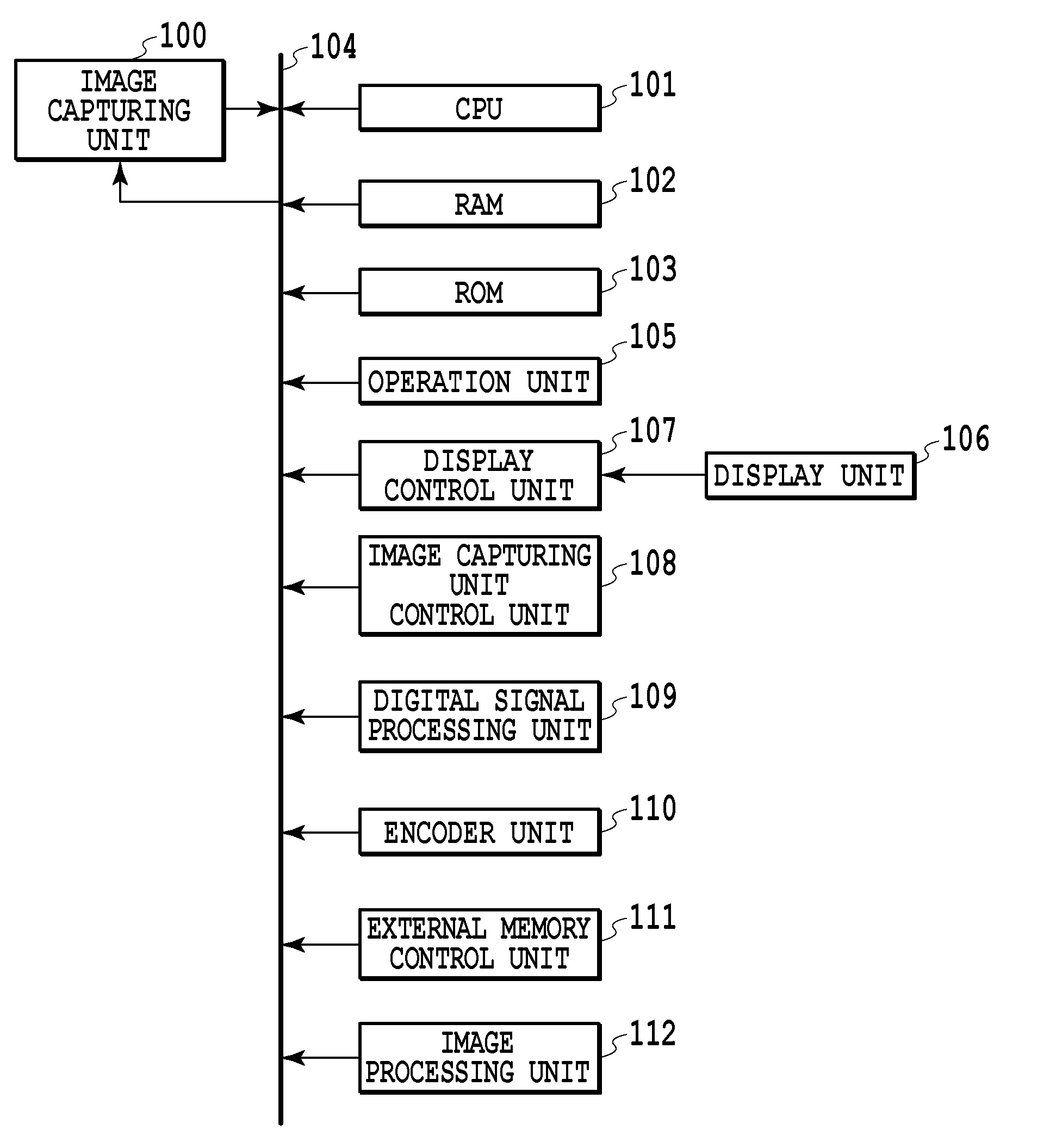
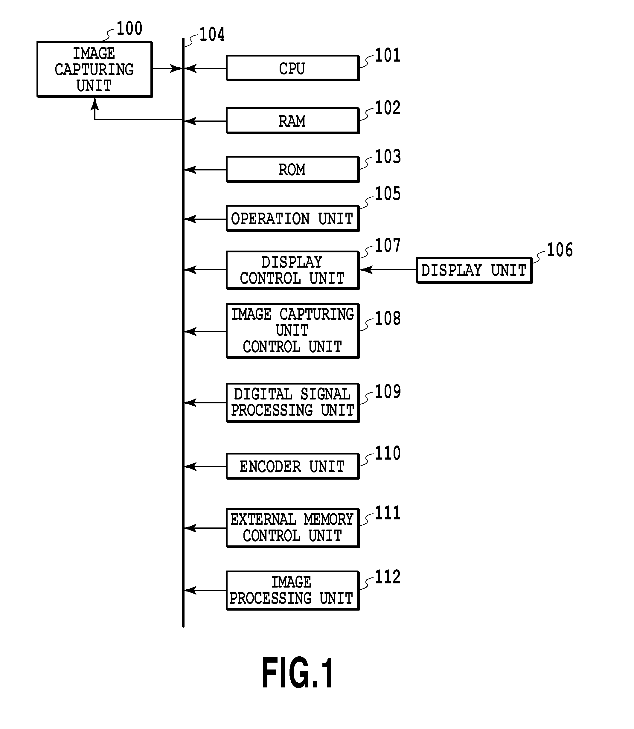
[0043]FIG. 1 is a block diagram showing an internal configuration of an image capturing device according to a first embodiment.

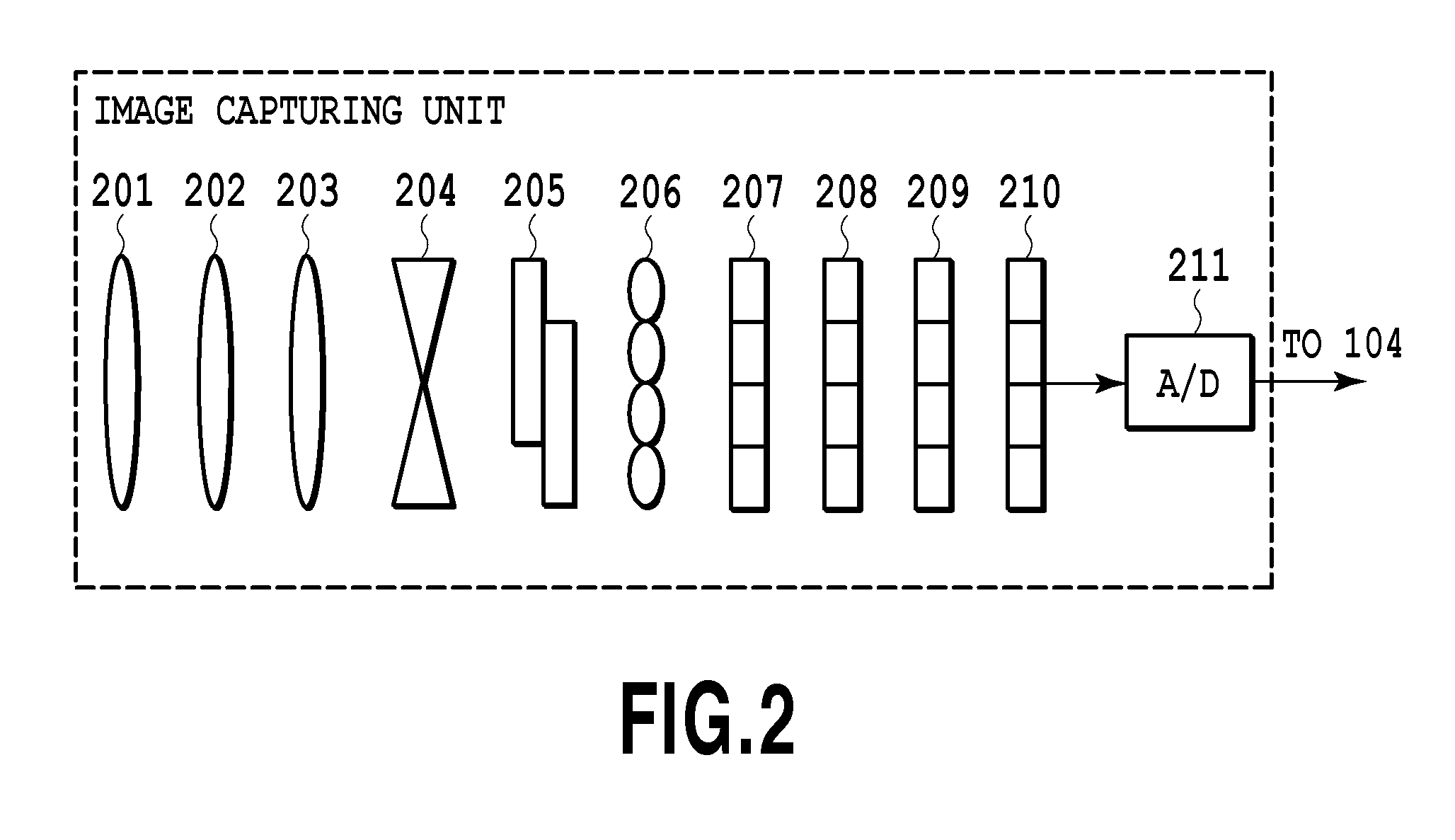
[0044]An image capturing unit 100 receives light information of a subject with an image sensing element and A / D converts the received signal to acquire color image data (digital data). Details of the image capturing unit 100 will be described later. A central processing unit (CPU) 101 totally controls each unit described below. A RAM 102 functions as a main memory, a work area etc., of the CPU 101. A ROM 103 stores control programs etc. executed by the CPU 101. A bus 104 is a transfer path of various kinds of data and for example, digital image data acquired by the image capturing unit 100 is sent to a predetermined processing unit via the bus 104. An operation unit 105 configured to receive a user's instruction includes buttons, mode dials, etc. In a display unit 106 configured to display captured images and characters, for example, a liquid crystal display...

second embodiment

[0129]The first embodiment is an aspect in which the f-stop (F-number) of the main lens selected at the time of calibration of the microlens array is set to a value relatively larger than the f-stop of the main lens at the time of final image capturing (the state where the aperture is stopped down). Next, an aspect is explained as a second embodiment, in which data of an image captured at the time of calibration is analyzed and an appropriate f-stop of the main lens is selected and then calibration of the microlens array is performed. Explanation of parts common to those of the first embodiment is simplified or omitted and here, the different points are explained mainly.

[0130]

[0131]FIG. 21 is a block diagram showing an internal configuration of the image processing unit 112 in the present embodiment. An image analyzing unit 2101 is added to the image processing unit 112 of the first embodiment explained in FIG. 8. The image analyzing unit 2101 analyzes data of an image captured for ...

third embodiment

[0168]The second embodiment is an aspect in which data of an image captured for calibration of the microlens array is analyzed and calibration is performed after selecting an appropriate f-stop (F-number) of the main lens. Next, an aspect is explained as a third embodiment, in which data of an image captured for calibration is analyzed and in the case that the data of the captured image is not suitable for calibration, warning to that effect is given to a user. Explanation of parts common to those of the second embodiment is simplified or omitted and here different points are explained mainly.

[0169]The internal configuration of the image processing unit 112 in the third embodiment is basically the same as the internal configuration of the image processing unit 112 shown in FIG. 21 according to the second embodiment. Although not shown schematically, the different point is that the analysis result of the image analyzing unit 2101 is sent also to the display control unit 107 in additi...


PUM


Abstract

By a conventional technique, it is not possible to provide an image refocused accurately at a desired subject distance. An image processing device is characterized by including an image data acquiring unit configured to acquire calibration image data obtained by an image capturing device including an aperture to adjust an amount of incident light, a lens array in which a plurality of lenses is arranged, and an image sensing element to photoelectrically convert an image of a subject via the lens array and obtained in a state where the aperture is stopped down in accordance with an instruction of calibration; and a unit configured to acquire a position of an image on the image sensing element corresponding to each of the lenses based on the calibration image data.

Description

BACKGROUND OF THE INVENTION[0001]1. Field of the Invention[0002]The present invention relates to calibration of a microlens array.[0003]2. Description of the Related Art[0004]Conventionally, when an image was captured by a camera was out of focus, it was necessary to recapture the image after re-performing focusing. Further, when obtaining focused images of a plurality of subjects at different depths, it was necessary to re-focus before capturing the image of each subject in focus.[0005]In recent years, a technique called light field photography has been developed, which is capable of acquiring images from multiple viewpoints by adding a new optical element into the optical system, and by adjusting the focus position in later image processing (refocus).[0006]By using this technique, there is an advantage that a failure in focusing at the time of image capture can be compensated for by image processing because it is possible to perform focusing after image capturing. Further, there i...

Claims


Application Information

Patent Timeline
IPC IPC(8): H04N17/00
CPCH04N5/232H04N17/002H04N23/67H04N23/634H04N23/631
Inventor TSUTSUMI, SHOHEI
Owner CANON KK
Why Eureka
Try Eureka